Applying Lenz’s Law

Nature abhors a change of flux.

D. J. Griffiths’ (2013) genius re-statement of Lenz’s Law, modelled on Aristotle’s historically influential but now debunked aphorism that ‘Nature abhors a vacuum’

A student recently asked for help with this AQA A-level Physics multiple choice question:

AQA A-level Physics question from 2019 Paper 2

This question is, of course, about Lenz’s Law of Electromagnetic Induction. The law can be stated easily enough: ‘An induced current will flow in a direction so that it opposes the change producing it.’ However, it can be hard for students to learn how to apply it.

What follows is my suggested explanatory sequence.

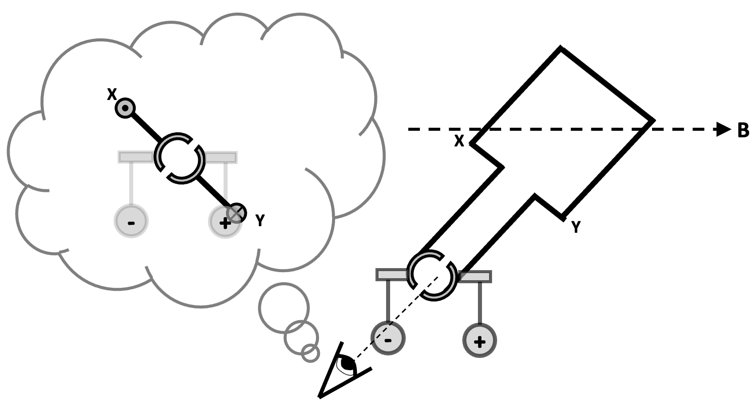
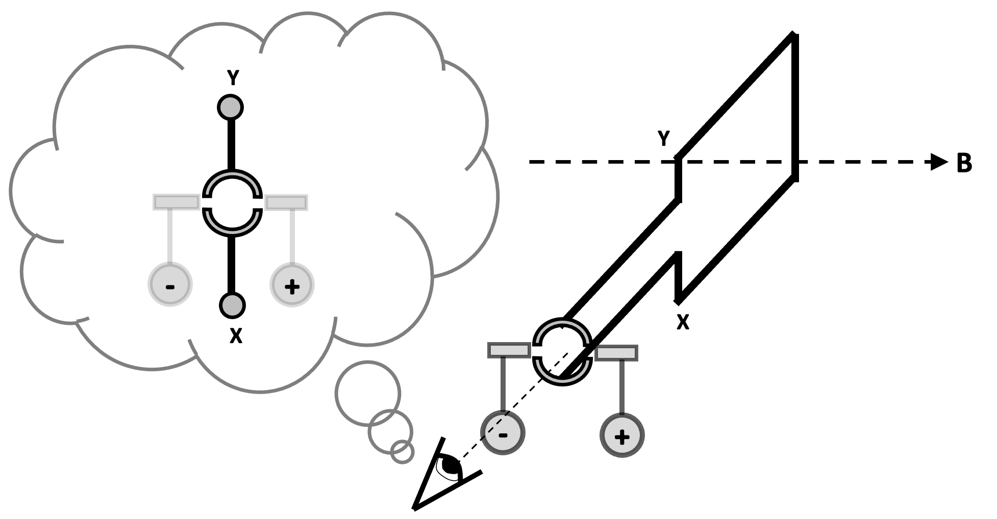
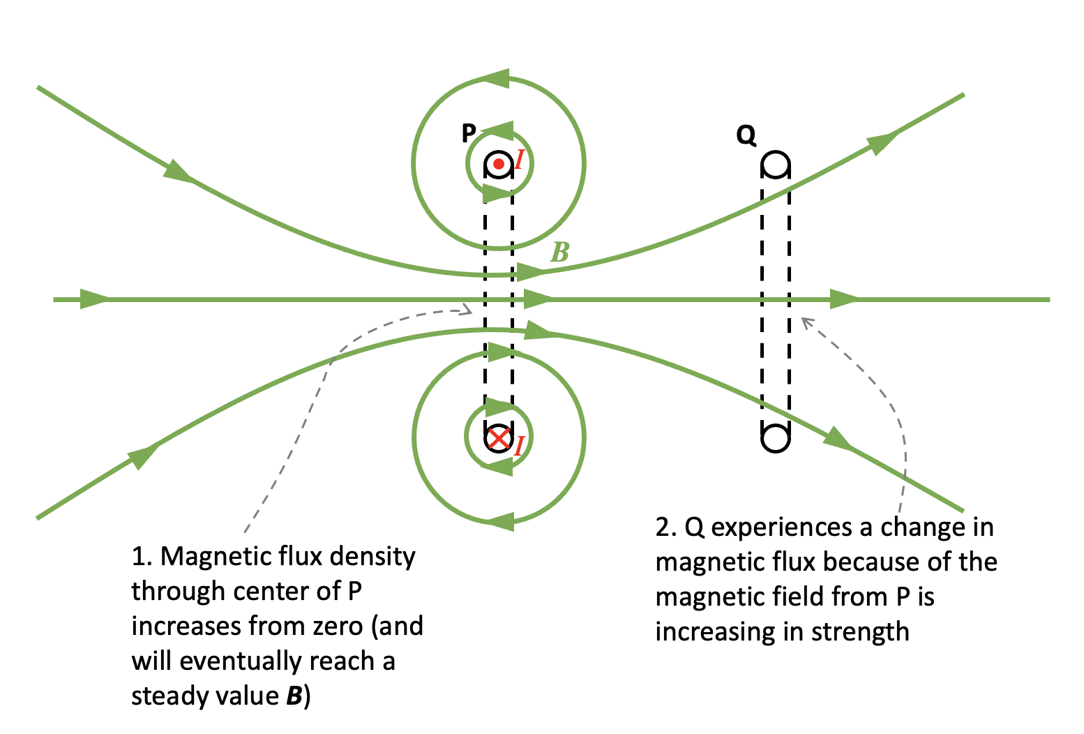
Step 1: simplify the diagram using the ‘dot and cross’ convention

When the switch is closed, a current I begins to flow in coil P. We can assume that I starts at zero and increases to a maximum value in a very small but not negligible period of time.

Simplified 2D representation of the top diagram. The current directions I are arbitrary based on my ‘best guess’ interpretation of the 3D diagram and could be reversed if desired.

Step 2: consider the magnetic field produced by P

You can read more about a simple method of deducing the direction of the magnetic field produced by a coil or a solenoid here.

Step 3: apply Faraday’s Law to coil Q

Since Q is experiencing a change in magnetic flux, then an induced current will flow through it.

Step 4: apply Lenz’s Law to coil Q

The current in coil Q must flow in such a direction so that it opposes the change producing it.

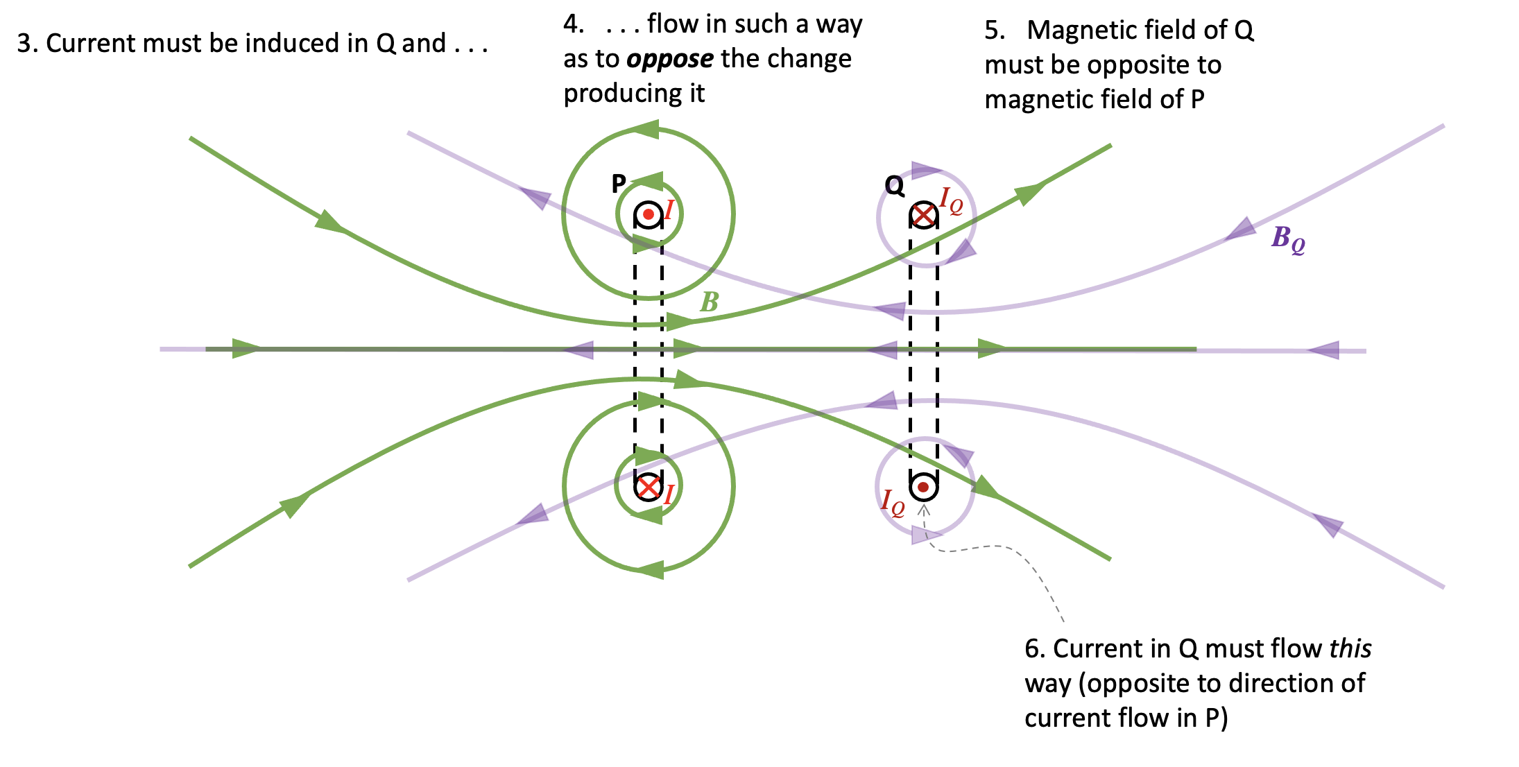
Since P is producing an increasing magnetic flux through Q, then the current in Q must flow in such a way so that it tries to prevent the increase in magnetic flux which is inducing it. The direction of the magnetic field BQ produced by Q must therefore be opposite to the direction of the magnetic field produced by P.

Step 5: consider the polarity of the magnetic fields of P and Q

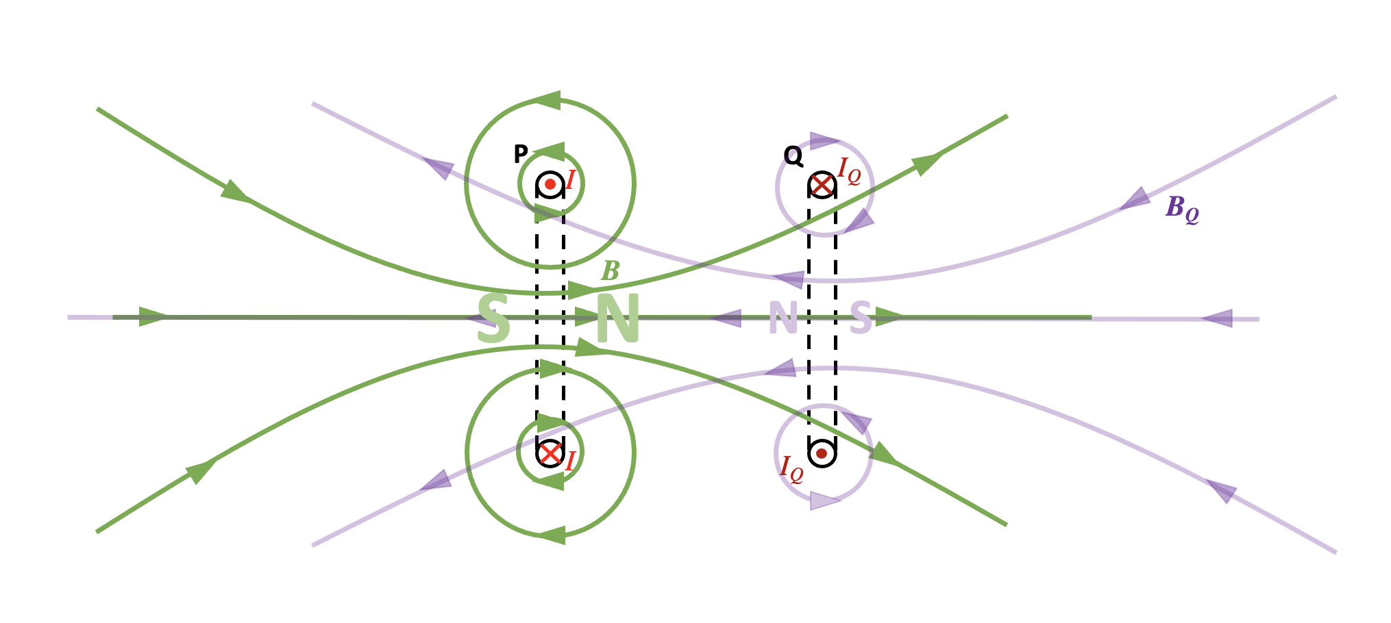
We can see the magnetic field lines of coil P produce a north magnetic field on its right hand side. The magnetic field of Q will produce a north magnetic field on its left hand side. Coil P will therefore push coil Q to the right.

It follows that we can eliminate options A and C from the question.

Step 6: What happens when the magnetic field of P reaches its steady value?

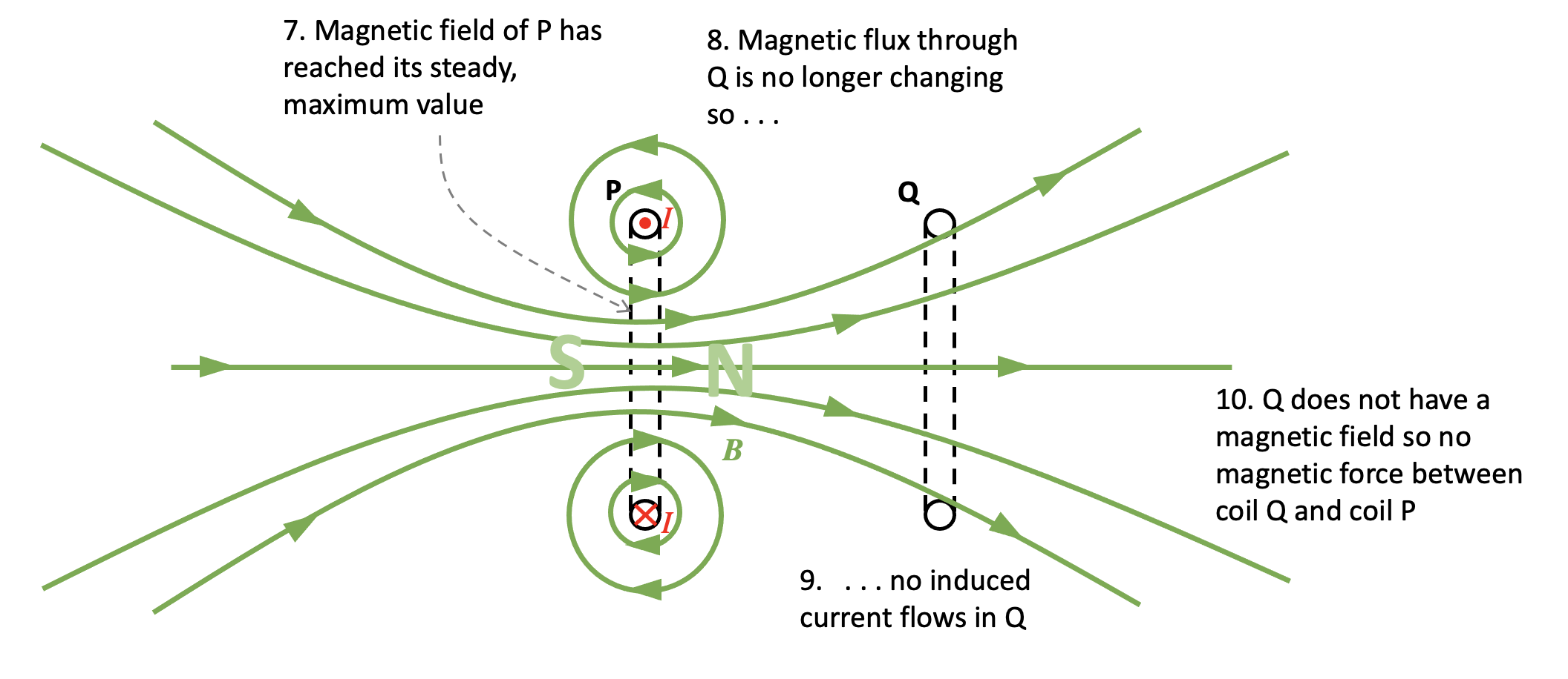
Because the magnetic field produced by coil P has how reached its steady maximum value, this means that the magnetic flux through coil Q also has a constant, unchanging value. Since there is no change in magnetic flux, then this means that no emf is induced across the coil so no induced current flows. Since Q does not have a magnetic field it follows that there is no magnetic interaction between them.

The answer to the question must therefore be D.

Step 7: check student understanding

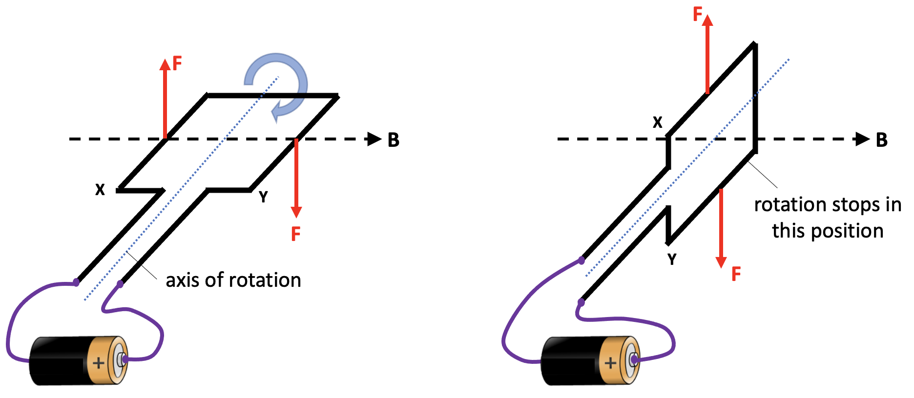
For the alternative question, the correct answer of C can be explained by going through a process similar to the one outlined above.

  • When the switch is opened, the magnetic flux through Y begins to decrease.
  • A changing magnetic flux through Y induces current flow.
  • Lenz’s Law predicts that the direction of this current is such that it opposes the change producing it.
  • The current through Y will therefore be in the same direction as the current through X to produce a magnetic field in the same direction.
  • The coils will attract each other.
  • Eventually, the magnetic flux produced by coil X drops to a constant value of zero.
  • Since there is no change in magnetic flux through Y, there is no induced current flow through Y and hence no magnetic field.
  • There is no magnetic interaction between X and Y and therefore the force on Y is zero.

Conclusion

I hope teachers find this detailed analysis of a Lenz’s Law question useful! As in much of A-level Physics, the devil is not in the detail but rather in the application of the detail. Students who encounter more examples will have a more secure understanding.

Reference

Griffiths, David (2013). Introduction to Electrodynamics. p. 315.

‘Isn’t it ionic?’: Showing the circular motion of charged particles in magnetic fields in the school laboratory

Charged particles which are stationary within a magnetic field do not experience a magnetic force; however, charged particles which are moving within a magnetic field most definitely do. And, what is more, this magnetic force or Lorentz force always makes them move on circular paths or semicircular paths. (Note: for simplicity we’re only going to look at particles whose velocity is perpendicular to the magnetic field lines in this post.) The direction of the Lorentz force can be predicted using Fleming’s Left Hand Rule.

An understanding of this type of interaction is essential for A-level Physics as far the physics of particle accelerators and cyclotrons are concerned. It is, of course, desirable to be able to demonstrate this to our students in the school laboratory. Your school may be lucky enough to own an electron beam tube and a pair of Helmholtz coils that is the usual way of displaying this phenomenon.

Bob Worley (@UncleBo80053383) recently made me aware of a low cost, microscale chemistry demonstration that I believe shows this phenomenon to good effect. If the electrolysis of sodium sulfate is carried out over a strong neodymium magnet then the interaction between the electric and magnetic fields creates clear patterns of circulation that are consistent with the directions predicted by the movement of the ions within the electric field produced by the electrodes and the Fleming’s Left Hand Rule force on the ions produced by the external magnetic field.

Please note that in the following post, any errors, omissions or misconceptions are my own (especially with the chemistry ‘bits’).

Why do charged particles move on circular paths when they travel through magnetic fields?

An electron beam tube. The electron beam is being made to move on a circular path by an external magnetic field.

In the diagram below, the green area represents a region of uniform magnetic flux density B. The field lines are directed into the plane of the diagram. Let’s consider an electron (1) fired at a horizontal velocity v from an electron gun as shown.

Fleming’s Left Hand Rule predicts that an upward force F will be produced on the electron. (Remember that the current in FLHR is conventional current so the ‘I’ finger should be pointed in the opposite direction to v because electron have a negative charge!) This will alter the direction of v so that the electron moves to position (2). Note that the magnitude of v is unaltered since F is acting at right angle to it. In position (2), FLHR again predicts a force F will act on the moving electron, and this force will again be at right angles to v resulting in the electron moving to position (3). Since the magnitude of v remains unaltered and F is always perpendicular to it, this means that F acts as a centripetal force which means that the electron travels at uniform speed around a circular orbit of radius r.

It can be shown that r = mv/Bq where m is the mass of the particle and q is its charge.

Setting up the electrolysis of sodium sulfate in a magnetic field

Electrolysis of sodium sulfate influenced by a magnet (side view)

The equipment is set up as shown in the diagram above. This can be seen from 0:00 to 0:10 seconds on the video. The magnetic field produced by the magnet can be thought of as a uniform vertical field through the volume of the drop.

Next, a few drops of red litmus are added. Since the sodium sulfate solution is neutral, the red litmus does not change colour.

At 0:15 seconds, the electrodes are introduced to the solution. Note that the anode is on the left and the cathode is on the right.

Observing the circular motion of charged particles in a magnetic field (part 1)

Almost immediately, we see indicator change colour next to the cathode. Since sodium sulfate is a salt produced using a reactive metal and an acid containing oxygen, the electrolysis will result in hydrogen gas at the cathode and oxygen at the anode. In other words, water will be electrolysed.

At the cathode, water molecules will be reduced to form H2 and OH.

It is the OH ions that produce the colour change to purple.

From 0:23 to 0:27 we can clearly an anticlockwise circulation pattern in the purple coloured region.

This can be explained by considering the forces on an OH ion as shown on the diagram below.

Electrolysis of sodium sulfate under the influence of a magnetic field (plan view)

As soon as it is created, the OH ion will be repelled away from the cathode along an electric field line (blue dotted lines). This means that it will be moving at a velocity v at the instant shown. However, due to the external magnetic field B it will also be subject to a Lorentz force F as shown (and whose direction can be predicted using Fleming’s Left Hand Rule) which will make it move on an anticlockwise circular path.

Because of the action of the electric field, the magnitude of v will increase meaning that that radius of circulation r of the OH ion will increase. This means that OH ion will travel on an anticlockwise spiral path of gradually increasing radius, as observed. This is analogous to paths followed by charged particles in a cyclotron.

Observing the circular motion of charged particles in a magnetic field (part 2)

At 0:29 seconds, we observe a second circulation pattern. We see the purple coloured solution begin a clockwise circulation around the anode.

This is because the OH ions gradually move towards the anode and eventually will begin moving at a radial velocity v towards it as shown. Fleming’s Left Hand Rule predicts a Lorentz force F will act on the ion as shown which means that it will move on a clockwise circular path.

The video from 0:30 to 0:35 shows at least some the ions moving on clockwise spiral path of decreasing radius. This is most likely because the magnitude of v of a number of ions is decreasing. The mechanism which produces this decrease of v is unknown (at least to me) but it seems plausible to suppose that a large number of OH ions arriving in the smaller region around the anode might produce a ‘traffic jam’ that would reduce the mean velocity of the ions here.

Conclusion

I hope physics teachers find this demonstration as useful and intriguing as I do. Please leave a comment if you decide to use it in your physics classroom. Many thanks to Bob Worley for posting the fascinating video!

Gears for GCSE Physics

I recently made a bit of a mess of teaching the topic of gears by trying to ‘wing it’ with insufficient preparation. To avoid my — and possibly others’ — future blushes, I thought I would compile a post summarising my interpretation of what students need to know about gears for AQA GCSE Physics.

I am going to include some handy gifs and a clean, un-annotated Google Jamboard (my favoured medium for lessons).

Any continuing errors, omissions or misconceptions are entirely my own fault.

‘A simple gear system can be used to transmit the rotational effect of a force’ [AQA 4.5.4]

A gear is a wheel with teeth that can transmit the rotational effect of a force.

For example, in the gear train shown above, the first gear (A) is turned by a motor (green dot shown below). The moment (rotational effect) is passed via the interlocking teeth to gear B and so on down the chain to gear E. It is also worth pointing out that gear A has a clockwise moment but gear B has an anticlockwise moment. The direction alternates as we move down the chain. It takes a gear train of five gears to transmit the clockwise moment from gear A to gear E.

Gears A-E are all equal in size with the same number of teeth and, consequently, the moment does not change in magnitude as it passes down the chain (although, as noted above, it does change direction from clockwise to anticlockwise).

‘Students should be able to explain how gears transmit the rotational effect of forces’ [AQA 4.5.4]

Part 1: A reduction gear arrangement

The driving gear (coloured blue) is smaller and has 6 teeth compared with the large gear’s 18 teeth. This is called a reduction gear arrangement.

A reduction gear arrangement does two things:

  1. It slows down the speed of rotation. You may notice that the large gear turns only one for each three turns of the small gear.
  2. The larger gear exerts a larger moment than the smaller gear. This is because the distance from the centre to the edge is larger for the grey gear.

The blue gear A exerts a force FA on gear B. By Newton’s Third Law, gear B exerts an equal but opposite force FB on gear A. Let’s take the magnitude of both forces to be F.

The anticlockwise moment exerted by gear A is given by m = F x d. The clockwise moment exerted by gear B is given by M=F x D. Since D > d then M > m.

A reduction gear arrangement is typically used in devices like an electric screwdriver. The electric motor in the device produces only a small rotational moment m but a large moment M is needed to turn the screws. The reduction gear produces the large moment M required.

Part 2: The overdrive arrangement

What happens when the driver gear is larger and has a greater number of teeth than the driven gear? This is called an overdrive arrangement.

The example we are going to look at is the arrangement of gears on a bicycle.

Here the driver gear (on the left) is linked via a chain to the smaller driven gear on the right. This means that the anticlockwise moment of the first gear is transmitted directly to the second gear as an anticlockwise moment. That is to say, the direction of the moment is not reversed as it is when the two gears are directly linked by interlocking teeth.

In the example shown, the big gear A turns only once for each four turns completed by the smaller gear B. Let’s assume that gear A exerts a force F on the chain so that the chain exerts an identical force F on gear B. Since D > d, this means that M > m so that the arrangement works as a distance multiplier rather than a force multiplier. This is, of course, excellent if we are riding at speed along a horizontal road. However, if we encounter an upward incline we may wish to — using the gear changing arrangement on the bike — swap the small gear B with one with a larger value of d. This would have the happy effect of increasing the magnitude of m so as to make it slightly easier to pedal uphill.

The annotate-able Jamboard is available here.

Acknowledgements

I used Gear Generator, Gear Generator 2 and EZgif to produce the gear animations.

Dual coding change of momentum

Rosencrantz (an anguished cry): CONSISTENCY IS ALL I ASK!

Tom Stoppard, Rosencrantz and Guildenstern Are Dead (1966)

I think that dual coding techniques can be extremely helpful in helping students understand the concept of change of momentum.

To engage our students’ physical intuitions, let’s consider a question like: Which would hurt more — being hit by a sandbag or being hit by a rubber ball?

Let’s assume that the sandbag and rubber ball have the same mass m and are travelling at the same initial velocity u. We choose ‘u‘ because it’s the initial velocity and we take ‘v‘ as the final velocity: a very subtle piece of dual coding that can reap rewards if applied consistently — pace Rosencrantz(!) — over a range of disparate examples.

To analyse this problem, let’s use the momentum version of Newton’s Second Law of Motion.

We will use the change = final – initial convention (‘Consistency is all I ask!’)). The initial momentum is pi and the final momentum is pf.

Now let’s work out the change in momentum in each case. We will assume that each item is dropped so that it impacts vertically on a horizontal surface. The velocity just before it hits is u so its initial momentum pi is given by pi = mu; its final velocity is v so its final momentum pf is given by pf = mv. The sandbag does not rebound, so its final velocity v is zero.

The rubber ball rebounds from the surface with a velocity v (we have shown that v < u so we are not assuming a perfectly elastic collision).

We will use the down-is-positive convention so that u is positive and the downward momentum pi are positive in both cases. However, the velocity v of the ball is negative so the momentum pf = mv is negative (upwards).

To add vectors, we simply put them ‘nose to tail’. However, in this case, we need to subtract the vectors, not add them. To do this, we use the operation pf + (-pi,). In other words, we put the vector pf nose to tail with minus pi, or with a vector pointing in the opposite direction to the original vector pi. These are shown in the table.

We can see that the change in momentum Δp is larger in the case of the rubber ball.

Applying Newton Second Law that force = change in momentum / change in time then (assuming the time of each interaction is the same) then we can conclude that the (upward) force exerted by the surface on the ball is larger than the force exerted by the surface on the sandbag.

From Newton’s Third Law (that if an object A exerts a force on object B, then object B exerts an equal and opposite force on object A), we can also conclude that the rubber exerts a larger downward force on the surface. This implies that, if the ball hit (say) your hand, then it would hurt more than the sandbag.

Considering change of momentum problems like this helps students answer questions such as the one shown below:

Exam question on change in momentum (solid black arrow and red arrow added)

We can discard options C and D since the change of momentum shown is in the wrong direction: the vertical component of momentum will remain unchanged.

A and B show changes of momentum of the same magnitude in the horizontal direction. However, if we take the horizontal component of the initial momentum as positive then the change of momentum on the gas particle must be negative; this implies that the correct answer is B.

Note also that diagram B shows the pf + (-pi) operation outlined above, with the arrow showing minus pi shown in red (added to the original exam question).

Introducing vectors (part 2)

This post suggests some strategies for teaching vectors to 14-16 olds. In part 1 we looked at the idea of combining two vectors into one; that is to say, finding the resultant vector. In this part, we’re going to look at the inverse operation: splitting a single vector into two component vectors.

We’re going to use scale drawing rather than trigonometry since (a) this often leads to a more secure understanding; and (b) it is the expected method in the UK curriculum for 14-16 year olds.

What is a component vector?

A component vector is one of at least two vectors that will combine to give one single original vector. The component vectors are chosen so that they are mutually perpendicular. Because of this, they cannot affect each other’s magnitude and direction and so can be dealt with separately and independently; that is to say, we can choose to consider what effect the vertical component will have on its own without having to worry about what effect the horizontal component will have.

Introducing components as ‘the vector less travelled by’

Two roads diverged in a wood, and I—
I took the one less traveled by,
And that has made all the difference.

Robert Frost, 'The Road Less Travelled'

Let’s say we travelled a distance of 13 m from point O to point P on a compass bearing of 067 degrees (bear with me, I’m working with a slightly less familiar Pythagorean 3:4:5 triple here). This could be drawn as a scale diagram as shown below.

Could we analyse the displacement OP in terms of an eastward displacement and a northward displacement?

We can — as shown below.

The dotted line OX is the eastward (horizontal on our diagram) component of the displacement OP. It is drawn as a dotted line because it is (literally) the ‘road less travelled’. We did not walk along that road — and that’s why it is drawn as a dotted line — but we could have done.

But let’s say that we had, and that we had stopped when we reached the point marked X. And then we look around, and strike out northwards and walk the (vertical) ‘road less travelled called XP — and we end up at P.

So walking one road less travelled might, indeed, make ‘all the difference’ — but walking two roads less travelled does not.

To rewrite Robert Frost: We took the two roads less travelled by / And that has made NO difference.

But why should we wish to go the ‘long way around’, even if we still end up at P? Because it would allow us to work out the change in longitude and latitude. By moving from O to P we change our longitude by 12 metres and our latitude by 5 metres. (Don’t believe me? Count the squares on the diagram!)

We have resolved the 13 metre distance into two components: one eastward (horizontal) component of 12 metres and one northward component of 5 metres.

Using resolving a vector into components to solve problems

We can use the scale drawing technique outlined above to resolve (‘split’) the 3000 N vector into a horizontal component and a vertical component.

The full solution is shown in sequence on this PowerPoint.

Just a moment . . .

Many years ago, I was taught this compact and intuitive convention to show turning moments. I think it should be more widely known, as it not only is concise and powerful, but also meets the criterion of being an effective form of dual coding which is helpful for both GCSE and A-level Physics students.

Let’s look at an example question.

Let’s start by ‘annotating the hell’ out of the diagram.

We could take moments around any of the marked points A-E on the diagram. However, we’re going to take moments around B as it enables us to ignore the upward reaction force acting on the rule at B. (This force is not shown on the diagram.)

To indicate that we’re going to be considering the sum of the clockwise moments about point B, we use this intuitive notation:

If we consider the sum of anticlockwise moments about point B, we use this:

We lay out our calculations of the total clockwise and anticlockwise moments about B as follows.

We show that we are going to apply the Principle of Moments (the sum of clockwise moments is equal to the sum of anticlockwise moments for an object in equilibrium) like this:

The rest, as they say, is not history but algebra:

I hope you find this ‘momentary’ convention useful(!)

Split ring commutator? More like split ring commuHATER!

Students find learning about electric motors difficult because:

  1. They find it hard to predict the direction of the force produced on a conductor in a magnetic field, either with or without Fleming’s Left Hand Rule.
  2. They find it hard to understand how a split ring commutator works.

In this post, I want to focus on a suggested teaching sequence for the action of a split ring commutator, since I’ve covered the first point in previous posts.

Who needs a ‘split ring commutator’ anyway?

We all do, if we are going to build electric motors that produce a continuous turning motion.

If we naively connected the ends of a coil to power supply, then the coil would make a partial turn and then lock in place, as shown below. When the coil is in the vertical position, then neither of the Fleming’s Left Hand Rule (FLHR) forces will produce a turning moment around the axis of rotation.

When the coil moves into this vertical position, two things would need to happen in order to keep the coil rotating continuously in the same direction.

  • The current to the coil needs to be stopped at this point, because the FLHR forces acting at this moment would tend to hold the coil stationary in a vertical position. If the current was cut at this time, then the momentum of the moving coil would tend to keep it moving past this ‘sticking point’.
  • The direction of the current needs to be reversed at this point so that we get a downward FLHR force acting on side X and an upward FLHR force acting on side Y. This combination of forces would keep the coil rotating clockwise.

This sounds like a tall order, but a little device known as a split ring commutator can help here.

One (split) ring to rotate them all

The word commutator shares the same root as commute and comes from the Latin commutare (‘com-‘ = all and ‘-mutare‘ = change) and essentially means ‘everything changes’. In the 1840s it was adopted as the name for an apparatus that ‘reverses the direction of electrical current from a battery without changing the arrangement of the conductors’.

In the context of this post, commutator refers to a rotary switch that periodically reverses the current between the coil and the external circuit. This rotary switch takes the form of a conductive ring with two gaps: hence split ring.

Tracking the rotation of a coil through a whole rotation

In this picture below, we show the coil connected to a dc power supply via two ‘brushes’ which rest against the split ring commutator (SRC). Current is flowing towards us through side X of the coil and away from us through side Y of the coil (as shown by the dot and cross 2D version of the diagram. This produces an upward FLHR force on side X and a downward FLHR force on side Y which makes the coil rotate clockwise.

Now let’s look at the coil when it has turned 45 degrees. We note that the SRC has also turned by 45 degrees. However, it is still in contact with the brushes that supply the current. The forces on side X and side Y are as noted before so the coil continues to turn clockwise.

Next, we look at the situation when the coil has turned by another 45 degrees. The coil is now in a vertical position. However, we see that the gaps in the SRC are now opposite the brushes. This means that no current is being supplied to the coil at this point, so there are no FLHR forces acting on sides X and side Y. The coil is free to continue rotating clockwise because of momentum.

Let’s now look at the situation when the coil has rotated a further 45 degrees to the orientation shown below. Note that the side of the SRC connected to X is now touching the brush connected to the positive side of the power supply. This means that current is now flowing away from us through side X (whereas previously it was flowing towards us). The current has reversed direction. This creates a downward FLHR force on side X and an upward FLHR force on side Y (since the current in Y has also reversed direction).

And a short time later when the coil has moved a total of180 degrees from its starting point, we can observe:

And later:

And later still:

And then:

And then eventually we get back to:

Summary

In short, a split ring commutator is a rotary switch in a dc electric motor that reverses the current direction through the coil each half turn to keep it rotating continuously.

A powerpoint of the images used is here:

And a worksheet that students can annotate (and draw the 2D versions of the diagrams!) is here:

I hope that this teaching sequence will allow more students to be comfortable with the concept of a split ring commutator — anything that results in a fewer split ring commuHATERS would be a win for me 😉

A Gnome-inal Value for ‘g’

The Gnome Experiment Kit from precision scale manufacturers Kern and Sohn.

. . . setting storms and billows at defiance, and visiting the remotest parts of the terraqueous globe.

Samuel Johnson, The Rambler, 17 April 1750

That an object in free fall will accelerate towards the centre of our terraqueous globe at a rate of 9.81 metres per second per second is, at best, only a partial and parochial truth. It is 9.81 metres per second per second in the United Kingdom, yes; but the value of both acceleration due to free fall and the gravitational field strength vary from place to place across the globe (and in the SI System of measurement, the two quantities are numerically equal and dimensionally equivalent).

For example, according to Hirt et al. (2013) the lowest value for g on the Earth’s surface is atop Mount Huascarán in Peru where g = 9.7639 m s-2 and the highest is at the surface of the Arctic Ocean where g = 9.8337 m s-2.

Why does g vary?

There are three factors which can affect the local value of g.

Firstly, the distribution of mass within the volume of the Earth. The Earth is not of uniform density and volumes of rock within the crust of especially high or low density could affect g at the surface. The density of the rocks comprising the Earth’s crust varies between 2.6 – 2.9 g/cm3 (according to Jones 2007). This is a variation of 10% but the crust only comprises about 1.6% of the Earth’s mass since the density of material in the mantle and core is far higher so the variation in g due this factor is probably of the order of 0.2%.

Secondly, the Earth is not a perfect sphere but rather an oblate spheroid that bulges at the equator so that the equatorial radius is 6378 km but the polar radius is 6357 km. This is a variation of 0.33% but since the gravitational force is proportional to 1/r2 let’s assume that this accounts for a possible variation of the order of 0.7% in the value of g.

Thirdly, the acceleration due to the rotation of the Earth. We will look in detail at the theory underlying this in a moment, but from our rough and ready calculations above, it would seem that this is the major factor accounting for any variation in g: that is to say, g is a minimum at the equator and a maximum at the poles because of the Earth’s rotation.


The Gnome Experiment

In 2012, precision scale manufacturers Kern and Sohn used this well-known variation in the value of g to embark on a highly successful advertising campaign they called the ‘Gnome Experiment’ (see link 1 and link 2).

Whatever units their lying LCD displays show, electronic scales don’t measure mass or even weight: they actually measure the reaction force the scales exert on the item in their top pan. The reading will be affected if the scales are accelerating.

In diagram A, the apple is not accelerating so the resultant upward force on the apple is exactly 0.981 N. The scales show a reading of 0.981/9.81 = 0.100 000 kg = 100.000 g (assuming, of course, that they are calibrated for use in the UK).

In diagram B, the apple and scales are in an elevator that is accelerating upward at 1.00 metres per second per second. The resultant upward force must therefore be larger than the downward weight as shown in the free body diagram. The scales show a reading of 1.081/9.81 – 0.110 194 kg = 110.194 g.

In diagram C, the the apple and scales are in an elevator that is accelerating downwards at 1.00 metres per second per second. The resultant upward force must therefore be smaller than the downward weight as shown in the free body diagram. The scales show a reading of 0.881/9.81 – 0.089 806 kg = 89.806 g.


Never mind the weight, feel the acceleration

Now let’s look at the situation the Kern gnome mentioned above. The gnome was measured to have a ‘mass’ (or ‘reaction force’ calibrated in grams, really) of 309.82 g at the South Pole.

Showing this situation on a diagram:

Looking at the free body diagram for Kern the Gnome at the equator, we see that his reaction force must be less than his weight in order to produce the required centripetal acceleration towards the centre of the Earth. Assuming the scales are calibrated for the UK this would predict a reading on the scales of 3.029/9.81= 0.30875 kg = 308.75 g.

The actual value recorded at the equator during the Gnome Experiment was 307.86 g, a discrepancy of 0.3% which would suggest a contribution from one or both of the first two factors affecting g as discussed at the beginning of this post.

Although the work of Hirt et al. (2013) may seem the definitive scientific word on the gravitational environment close to the Earth’s surface, there is great value in taking measurements that are perhaps more directly understandable to check our comprehension: and that I think explains the emotional resonance that many felt in response to the Kern Gnome Experiment. There is a role for the ‘artificer’ as well as the ‘philosopher’ in the scientific enterprise on which humanity has embarked, but perhaps Samuel Johnson put it more eloquently:

The philosopher may very justly be delighted with the extent of his views, the artificer with the readiness of his hands; but let the one remember, that, without mechanical performances, refined speculation is an empty dream, and the other, that, without theoretical reasoning, dexterity is little more than a brute instinct.

Samuel Johnson, The Rambler, 17 April 1750

References

Hirt, C., Claessens, S., Fecher, T., Kuhn, M., Pail, R., & Rexer, M. (2013). New ultrahigh‐resolution picture of Earth’s gravity fieldGeophysical research letters40(16), 4279-4283.

Jones, F. (2007). Geophysics Foundations: Physical Properties: Density. University of British Columbia website, accessed on 2/5/21.

<

Teaching Newton’s Third Law

Newton’s First and Second Laws of Motion are universal: they tell us how any set of forces will affect any object.

The “Push-Me-Pull-You” made famous by Dr Doolittle

If the forces are ‘balanced’ (dread word! — saying ‘total force is zero’ is better, I think) then the object will not accelerate: that is the essence of the First Law. If the sum of the forces is anything other than zero, then the object will accelerate; and what is more, it will accelerate at a rate that is directly proportional to the total force and inversely proportional to the mass of the object; and let’s not forget that it will also accelerate in the direction in which the total force acts. Acceleration is, after all, a vector quantity.

So far, so good. But what about the Third Law? It goes without saying, I hope, that Newton’s Third Law is also universal, but it tells us something different from the first two.

The first two tell us how forces affect objects; the third tells us how objects affect objects: in other words, how objects interact with each other.

The word ‘interact’ can be defined as ‘to act in such a way so as to affect each other’; in other words, how an action produces a reaction. However, the word ‘reaction’ has some unhelpful baggage. For example, you tap my knee (lightly!) with a hammer and my leg jerks. This is a reaction in the biological sense but not in the Newtonian sense; this type of reaction (although involuntary) requires the involvement of an active nervous system and an active muscle system. Because of this, there is a short but unavoidable time delay between the stimulus and the response.

The same is not true of a Newton Third Law reaction: the action and reaction happen simultaneously with zero time delay. The reaction is also entirely passive as the force is generated by the mere fact of the interaction and requires no active ‘participation’ from the ‘acted upon’ object.

I try to avoid the words ‘action’ and ‘reaction’ in statements of Newton’s Third Law for this reason.

If body A exerts a force on body B, then body B exerts an equal and opposite force on body A.

The best version of Newton’s Third Law (imho)

In our universe, body B simply cannot help but affect body A when body A acts on it. Newton’s Third Law is the first step towards understanding that of necessity we exist in an interconnected universe.


Getting the Third Law wrong…

Let’s consider a stationary teapot. (Why not?)

This is NOT a good illustation of Newton’s Third Law…

We can reject this as an appropriate example of Newton’s Third Law for two reasons:

  • Reason 1: Force X and Force Y are acting on a single object. Newton’s Third Law is about the forces produced by an interaction between objects and so cannot be illustrated by a single object.
  • Reason 2: Force X and Force Y are ‘equal’ only in the parochial and limited sense of being merely ‘equal in magnitude’ (8.2 N). They are very different types of force: X is an action-at-distance gravitational force and Y is an electromagnetic contact force. (‘Electromagnetic’ because contact forces are produced by electrons in atoms repelling the electrons in other atoms.) The word ‘equal’ in Newton’s Third Law does some seriously heavy lifting…

Getting the Third Law right…

The Third Law deals with the forces produced by interactions and so cannot be shown using a single diagram. Free body diagrams are the answer here (as they are in a vast range of mechanics problems).

This is a good illustration of Newton’s Third Law

The Earth (body A) pulls the teapot (body B) downwards with the force X so the teapot (body B) pulls the Earth (body A) upwards with the equal but opposite force W. They are both gravitational forces and so are both colour-coded black on the diagram because they are a ‘Newton 3 pair’.

It is worth noting that, applying Newton’s Second Law (F=ma), the downward 8.2 N would produce an acceleration of 9.8 metres per second per second on the teapot if it was allowed to fall. However, the upward 8.2 N would produce an acceleration of only 0.0000000000000000000000014 metres per second per second on the rather more massive planet Earth. Remember that the acceleration produced by the resultant force is inversely proportional to the mass of the object being accelerated.

Similarly, the Earth’s surface pushes upward on the teapot with the force Y and the teapot pushes downward on the Earth’s surface with the force Z. These two forces form a Newton 3 pair and so are colour-coded red on the diagram.

We can summarise this in the form of a table:


Testing understanding

One the best exam questions to test students’ understanding of Newton’s Third Law (at least in my opinion) can be found here. It is a really clever question from the legacy Edexcel specificiation which changed the way I thought about Newton’s Third Law because I was suddenly struck by the thought that the only force that we, as humans, have direct control over is force D on the diagram below. Yes, if D increases then B increases in tandem, but without the weighty presence of the Earth we wouldn’t be able to leap upwards…

The Force Is Zero With This One

There is nothing absurd about perpetual motion; everywhere we look—at the planets wheeling around the Sun, or the electrons circling the heart of the atom—we see examples of it. Where there is no friction, as in airless space, an object can keep moving forever.

Arthur C. Clarke, Things That Can Never Be Done (1972)

So, according to Arthur C. Clarke, famous author and originator of the idea of the geosynchronous communications satellite, perpetual motion is no big deal. What is a big deal, of course, is arranging for such perpetual motion to occur on Earth. This is a near impossibilty, although we can get close: Clarke suggests magnetically suspending a heavy flywheel in a vacuum. (He also goes on to make the point that perpetual motion machines that can do useful external work while they run are, in fact, utterly impossible.)

The lack of visible examples of perpetual motion on Earth is, I think, why getting students to accept Newton’s First Law of Motion is such a perpetual struggle.

Newton’s First Law of Motion

Every body continues in its state of rest or uniform motion in a straight line, except insofar as it doesn’t.

A. S. Eddington, The Nature Of The Physical World (1958)

I think Sir Arthur Eddington was only half-kidding when he mischieviously rewrote the First Law as above. There is a sense where the First Law is superfluous.

It is superfluous because, technically, it is subsumed by the more famous Second Law which can be stated as F=ma where F is the resultant (or total) force acting on an object. Where the acceleration a is zero, as it would be for ‘uniform motion in a straight line’, then the resultant force is zero.

However, the point of the First Law is to act as the foundation stone of Newtonian dynamics: any deviation of an object from a straight line path is taken as implying the existence of a resultant force; if there is no deviation there no force and vice versa.

The First Law is an attempt to reset our Earth-centric intuition that a resultant force is needed to keep things moving, rather than change the perpetual motion of an object. In other words, our everyday, lived experience that to make (say) a box of books move with uniform motion in a straight line we need to keep pushing is wrong

Newton’s First Law, for real this time

A more modern formulation of Newton’s First Law might read:

An object experiencing zero resultant force will either: (a) remain stationary; or, (b) keep moving a constant velocity.

In my experience, students generally have no difficulty accepting clause (a) as long as they understand what we mean by a ‘zero resultant force’. As in so many things, example is possibly the best teacher:

The meaning of zero and non-zero resultant force

Clause (b) uses the concept of ‘constant velocity’ to avoid the circuitous ‘uniform motion in a straight line’. It is this second clause which gives many students difficulty because they hold the misconception that force is needed to sustain motion rather than change it.

And, truth be told, bearing in mind what students’ lived experience of motion on Earth is, it’s easy to see why they find clause (b) so uncongenial.

Is there any way of making clause (b) more palatable to your typical GCSE student?

Galileo, Galileo — magnifico!

Galileo, Galileo,
Galileo, Galileo,
Galileo Figaro - magnifico!

Queen, Bohemian Rhapsody

Galileo Galilei was one of the giants on whose shoulders Newton stood. His principle of inertia anticipated Newton’s First Law by nearly a century.

What follows is a variation of a ‘thought experiment’ that Galileo advanced in support of the principle of inertia; that is to say, that objects will continue moving at a constant velocity unless they are acted on by a resultant force. (A similar version from the IoP can be found here.)

Galileo’s U-shaped Track for the principle of inertia

Picture a ball placed at point A on the track and released.

Galieo’s U-shaped track (1/4): what we see in the real world…

What we see is the ball oscillating back and forth along the track. However, what we also observe is that the height reached by the ball gradually decreases. This is because of resistive forces that slow down the ball (e.g. friction between the track and the ball and air resistance).

What would happen if we stretched out one side of the curve to make a flat line?

Galieo’s U-shaped track (2/4): an extrapolation from what we see in the real world…

We surmise that the ball would come to a stop at some distant point B because of the same resistive forces we observed above.

Next, we return to the U-shaped track and think about what would happen if we lived in a world without any resistive forces.

Galieo’s U-shaped track (3/4): an extrapolation of what we would see in a world with no resistive forces…

The ball would oscillate back-and-forth between A and B. The height would not decrease as there would be no resistive forces.

Finally, what would happen in our imaginary, perfectly frictionless world if we stretched out one side of the ‘U’?

Galieo’s U-shaped track (4/4): a further extrapolation of what we might see in a world with no resistive force…

The ball would keep moving at a constant velocity because there would be no resistive forces to make it slow down.

This, then, is the way things move when no forces are acting on them: when the (resultant) force is zero, in other words.

Conclusion

Galileo framed the argument above (although he used a V-shaped track rather than a U-shaped one) to persuade a ‘tough crowd’ of Aristotleans of the plausibility of the principle of inertia.

In my experience, it can be a helpful argument to persuade even a ‘tough crowd’ of GCSE students to look at the world anew through a Newtonian lens…

Postscript

My excellent edu-Twitter colleague Matt Perks (@dodiscimus) points out that you can model Galileo’s U-shaped track using the PhET Energy Skate Park simulation and that you can even set the value of friction to zero and other values.

Click on the link above, select Playground, build a U-shaped track, set the friction slider to a certain value and away you go!

Using the PhET Energy Skate Park to model Galileo’s U-shaped track
You can even model the decrease in speed because of frictional forces!

This could be a real boon to helping students visualise the thought experiment.