D. J. Griffiths’ (2013) genius re-statement of Lenz’s Law, modelled on Aristotle’s historically influential but now debunked aphorism that ‘Nature abhors a vacuum’
A student recently asked for help with this AQA A-level Physics multiple choice question:
AQA A-level Physics question from 2019 Paper 2
This question is, of course, about Lenz’s Law of Electromagnetic Induction. The law can be stated easily enough: ‘An induced current will flow in a direction so that it opposes the change producing it.’ However, it can be hard for students to learn how to apply it.
What follows is my suggested explanatory sequence.
Step 1: simplify the diagram using the ‘dot and cross’ convention
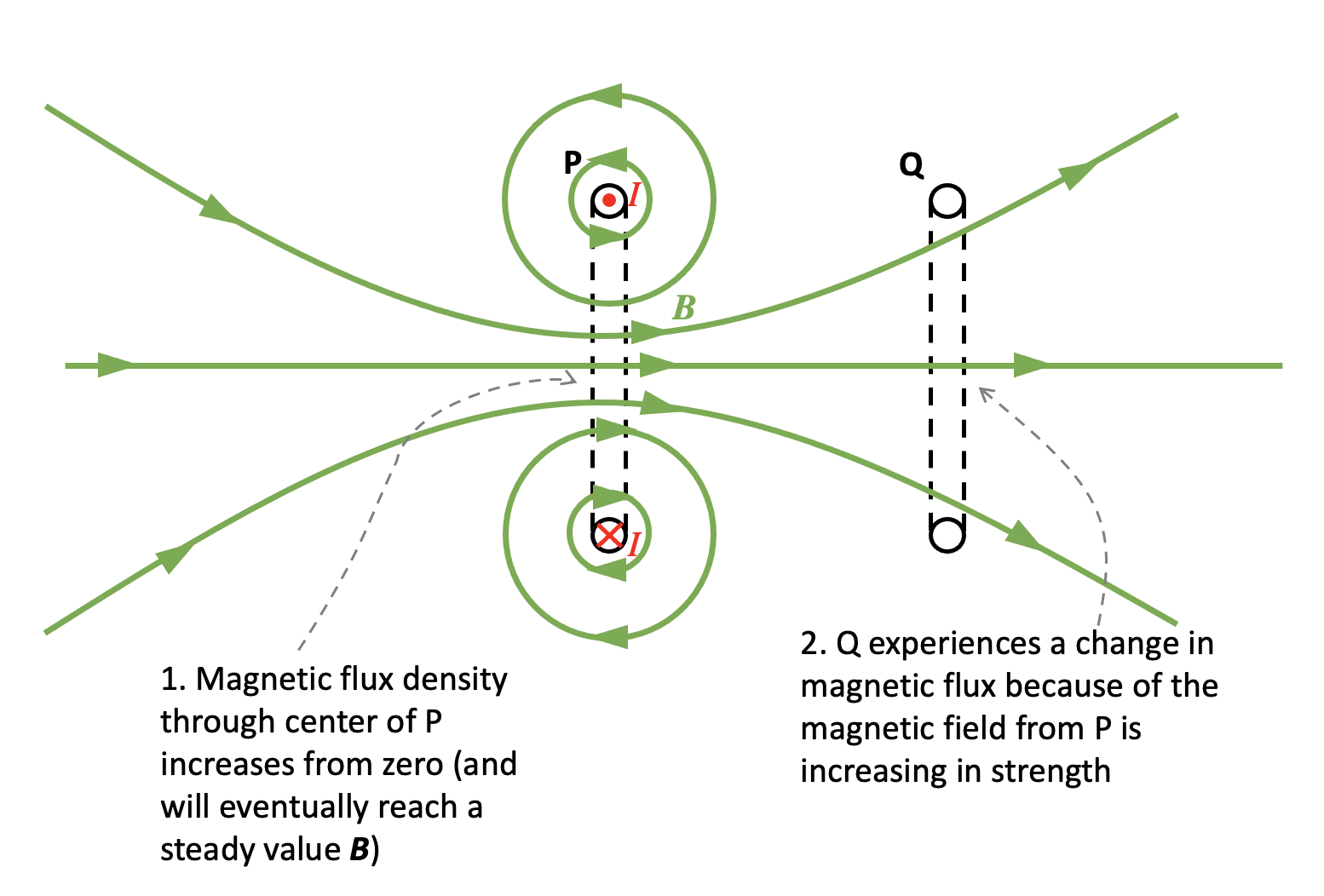
When the switch is closed, a current I begins to flow in coil P. We can assume that I starts at zero and increases to a maximum value in a very small but not negligible period of time.
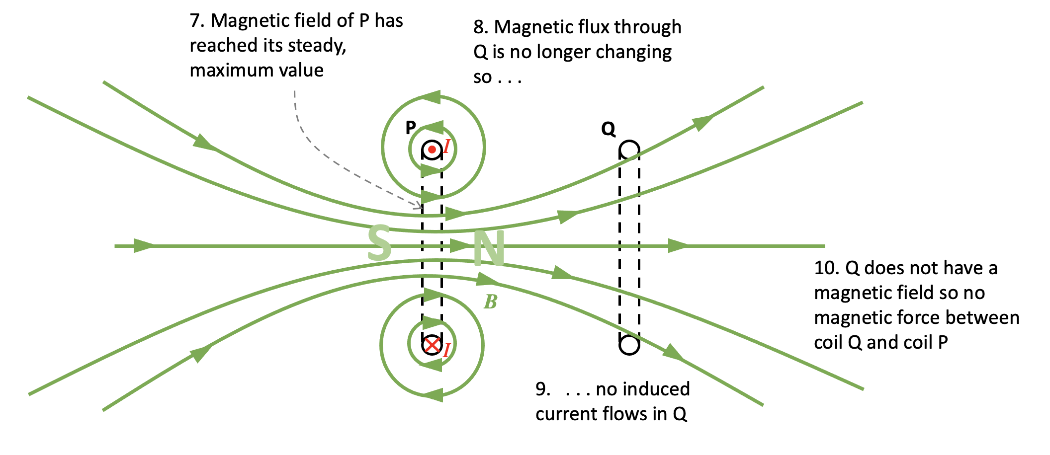
Simplified 2D representation of the top diagram. The current directions I are arbitrary based on my ‘best guess’ interpretation of the 3D diagram and could be reversed if desired.
Step 2: consider the magnetic field produced by P
You can read more about a simple method of deducing the direction of the magnetic field produced by a coil or a solenoid here.
Step 3: apply Faraday’s Law to coil Q
Since Q is experiencing a change in magnetic flux, then an induced current will flow through it.
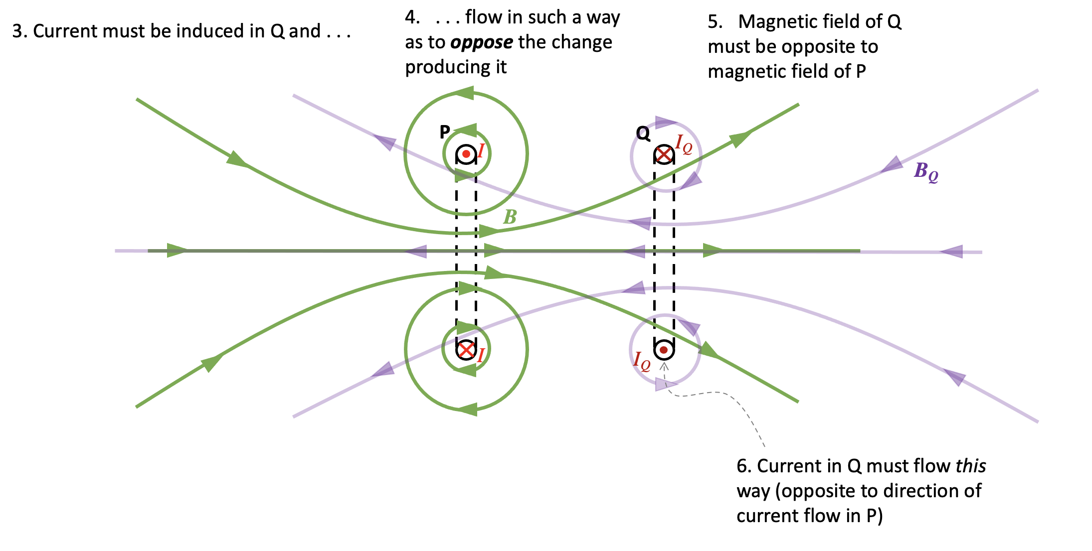
Step 4: apply Lenz’s Law to coil Q
The current in coil Q must flow in such a direction so that it opposes the change producing it.
Since P is producing an increasing magnetic flux through Q, then the current in Q must flow in such a way so that it tries to prevent the increase in magnetic flux which is inducing it. The direction of the magnetic field BQ produced by Q must therefore be opposite to the direction of the magnetic field produced by P.
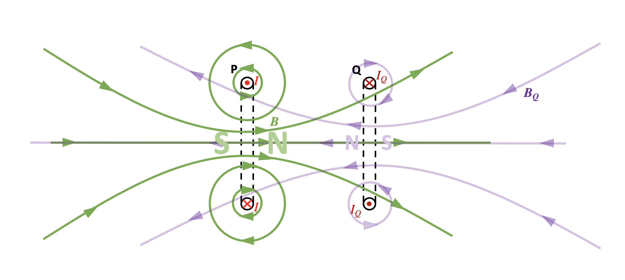
Step 5: consider the polarity of the magnetic fields of P and Q
We can see the magnetic field lines of coil P produce a north magnetic field on its right hand side. The magnetic field of Q will produce a north magnetic field on its left hand side. Coil P will therefore push coil Q to the right.
It follows that we can eliminate options A and C from the question.
Step 6: What happens when the magnetic field of P reaches its steady value?
Because the magnetic field produced by coil P has how reached its steady maximum value, this means that the magnetic flux through coil Q also has a constant, unchanging value. Since there is no change in magnetic flux, then this means that no emf is induced across the coil so no induced current flows. Since Q does not have a magnetic field it follows that there is no magnetic interaction between them.
The answer to the question must therefore be D.
Step 7: check student understanding
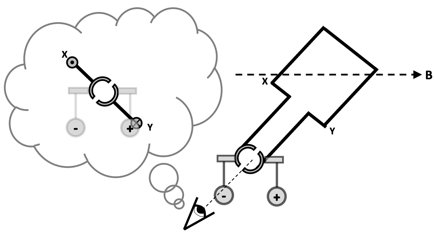
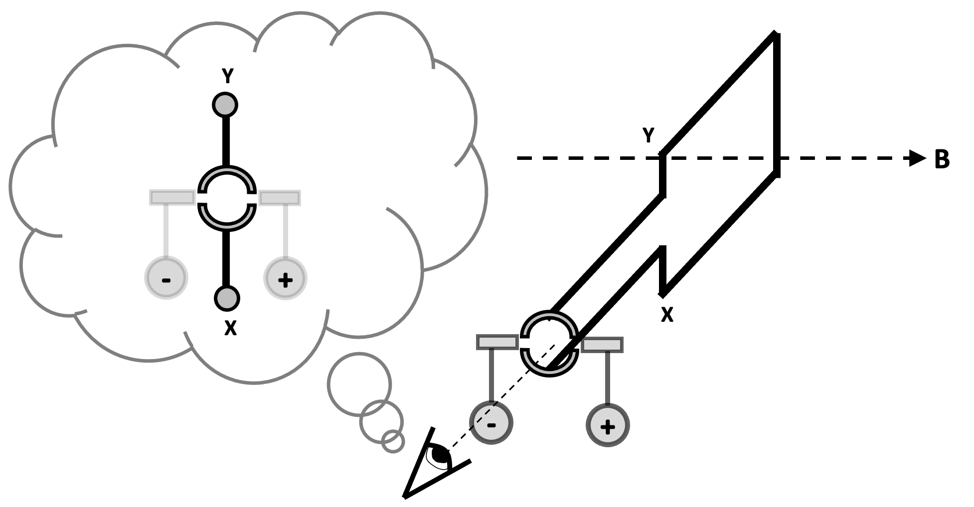
For the alternative question, the correct answer of C can be explained by going through a process similar to the one outlined above.
When the switch is opened, the magnetic flux through Y begins to decrease.
A changing magnetic flux through Y induces current flow.
Lenz’s Law predicts that the direction of this current is such that it opposes the change producing it.
The current through Y will therefore be in the same direction as the current through X to produce a magnetic field in the same direction.
The coils will attract each other.
Eventually, the magnetic flux produced by coil X drops to a constant value of zero.
Since there is no change in magnetic flux through Y, there is no induced current flow through Y and hence no magnetic field.
There is no magnetic interaction between X and Y and therefore the force on Y is zero.
Conclusion
I hope teachers find this detailed analysis of a Lenz’s Law question useful! As in much of A-level Physics, the devil is not in the detail but rather in the application of the detail. Students who encounter more examples will have a more secure understanding.
Reference
Griffiths, David (2013). Introduction to Electrodynamics. p. 315.
Charged particles which are stationary within a magnetic field do not experience a magnetic force; however, charged particles which are moving within a magnetic field most definitely do. And, what is more, this magnetic force or Lorentz force always makes them move on circular paths or semicircular paths. (Note: for simplicity we’re only going to look at particles whose velocity is perpendicular to the magnetic field lines in this post.) The direction of the Lorentz force can be predicted using Fleming’s Left Hand Rule.
An understanding of this type of interaction is essential for A-level Physics as far the physics of particle accelerators and cyclotrons are concerned. It is, of course, desirable to be able to demonstrate this to our students in the school laboratory. Your school may be lucky enough to own an electron beam tube and a pair of Helmholtz coils that is the usual way of displaying this phenomenon.
Bob Worley (@UncleBo80053383) recently made me aware of a low cost, microscale chemistry demonstration that I believe shows this phenomenon to good effect. If the electrolysis of sodium sulfate is carried out over a strong neodymium magnet then the interaction between the electric and magnetic fields creates clear patterns of circulation that are consistent with the directions predicted by the movement of the ions within the electric field produced by the electrodes and the Fleming’s Left Hand Rule force on the ions produced by the external magnetic field.
Please note that in the following post, any errors, omissions or misconceptions are my own (especially with the chemistry ‘bits’).
Why do charged particles move on circular paths when they travel through magnetic fields?
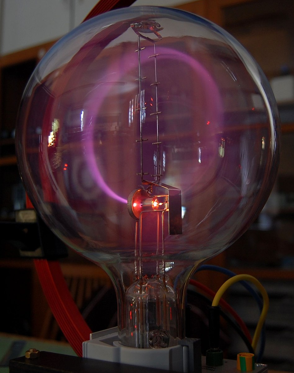
An electron beam tube. The electron beam is being made to move on a circular path by an external magnetic field.
In the diagram below, the green area represents a region of uniform magnetic flux density B. The field lines are directed into the plane of the diagram. Let’s consider an electron (1) fired at a horizontal velocity v from an electron gun as shown.
Fleming’s Left Hand Rule predicts that an upward force F will be produced on the electron. (Remember that the current in FLHR is conventional current so the ‘I’ finger should be pointed in the opposite direction to v because electron have a negative charge!) This will alter the direction of v so that the electron moves to position (2). Note that the magnitude of v is unaltered since F is acting at right angle to it. In position (2), FLHR again predicts a force F will act on the moving electron, and this force will again be at right angles to v resulting in the electron moving to position (3). Since the magnitude of v remains unaltered and F is always perpendicular to it, this means that F acts as a centripetal force which means that the electron travels at uniform speed around a circular orbit of radius r.
It can be shown that r = mv/Bq where m is the mass of the particle and q is its charge.
Setting up the electrolysis of sodium sulfate in a magnetic field
Electrolysis of sodium sulfate influenced by a magnet (side view)
The equipment is set up as shown in the diagram above. This can be seen from 0:00 to 0:10 seconds on the video. The magnetic field produced by the magnet can be thought of as a uniform vertical field through the volume of the drop.
Next, a few drops of red litmus are added. Since the sodium sulfate solution is neutral, the red litmus does not change colour.
At 0:15 seconds, the electrodes are introduced to the solution. Note that the anode is on the left and the cathode is on the right.
Observing the circular motion of charged particles in a magnetic field (part 1)
Almost immediately, we see indicator change colour next to the cathode. Since sodium sulfate is a salt produced using a reactive metal and an acid containing oxygen, the electrolysis will result in hydrogen gas at the cathode and oxygen at the anode. In other words, water will be electrolysed.
At the cathode, water molecules will be reduced to form H2 and OH–.
It is the OH– ions that produce the colour change to purple.
From 0:23 to 0:27 we can clearly an anticlockwise circulation pattern in the purple coloured region.
This can be explained by considering the forces on an OH– ion as shown on the diagram below.
Electrolysis of sodium sulfate under the influence of a magnetic field (plan view)
As soon as it is created, the OH– ion will be repelled away from the cathode along an electric field line (blue dotted lines). This means that it will be moving at a velocity v at the instant shown. However, due to the external magnetic field B it will also be subject to a Lorentz force F as shown (and whose direction can be predicted using Fleming’s Left Hand Rule) which will make it move on an anticlockwise circular path.
Because of the action of the electric field, the magnitude of v will increase meaning that that radius of circulation r of the OH– ion will increase. This means that OH– ion will travel on an anticlockwise spiral path of gradually increasing radius, as observed. This is analogous to paths followed by charged particles in a cyclotron.
Observing the circular motion of charged particles in a magnetic field (part 2)
At 0:29 seconds, we observe a second circulation pattern. We see the purple coloured solution begin a clockwise circulation around the anode.
This is because the OH– ions gradually move towards the anode and eventually will begin moving at a radial velocity v towards it as shown. Fleming’s Left Hand Rule predicts a Lorentz force F will act on the ion as shown which means that it will move on a clockwise circular path.
The video from 0:30 to 0:35 shows at least some the ions moving on clockwise spiral path of decreasing radius. This is most likely because the magnitude of v of a number of ions is decreasing. The mechanism which produces this decrease of v is unknown (at least to me) but it seems plausible to suppose that a large number of OH– ions arriving in the smaller region around the anode might produce a ‘traffic jam’ that would reduce the mean velocity of the ions here.
Conclusion
I hope physics teachers find this demonstration as useful and intriguing as I do. Please leave a comment if you decide to use it in your physics classroom. Many thanks to Bob Worley for posting the fascinating video!
They do observe I grow to infinite purchase, The left hand way;
John Webster, The Duchess of Malfi
Electromagnetic induction — the fact that moving a conductor inside a magnetic field in a certain direction will generate (or induce) a potential difference across its ends — is one of those rare-in-everyday-life phenomena that students very likely will never have come across before. In their experience, potential differences have heretofore been produced by chemical cells or by power supply units that have to be plugged into the mains supply. Because of this, many of them struggle to integrate electromagnetic induction (EMI) into their physical schema. It just seems such a random, free floating and unconnected fact.
What follows is a suggested teaching sequence that can help GCSE-level students accept the physical reality of EMI without outraging their physical intuition or appealing to a sketchily-explained idea of ‘cutting the field lines’.
‘Look, Ma! No electrical cell!’
I think it is immensely helpful for students to see a real example of EMI in the school laboratory, using something like the arrangement shown below.
A length of copper wire used to cut the magnetic field between two Magnadur magnets on a yoke will induce (generate) a small potential difference of about 5 millivolts. What is particularly noteworthy about doing this as a class experiment is how many students ask ‘How can there be a potential difference without a cell or a power supply?’
The point of this experiment is that in this instance the student is the power supply: the faster they plunge the wire between the magnets then the larger the potential difference that will be induced. Their kinetic energy store is being used to generate electrical power instead of the more usual chemical energy store of a cell.
But how to explain this to students?
A common option at this point is to start talking about the conductor cutting magnetic field lines: this is hugely valuable, but I recommend holding fire on this picture for now — at least for novice learners.
What I suggest is that we explain EMI in terms of a topic that students will have recently covered: the motor effect.
This has two big ‘wins’:
It gives a further opportunity for students to practice and apply their knowledge of the motor effect.
Students get the chance to explain an initially unknown phenomenon (EMI) in terms of better understood phenomenon (motor effect). The motor effect will hopefully act as the footing (to use a term from the construction industry) for their future understanding of EMI.
Explaining EMI using the motor effect
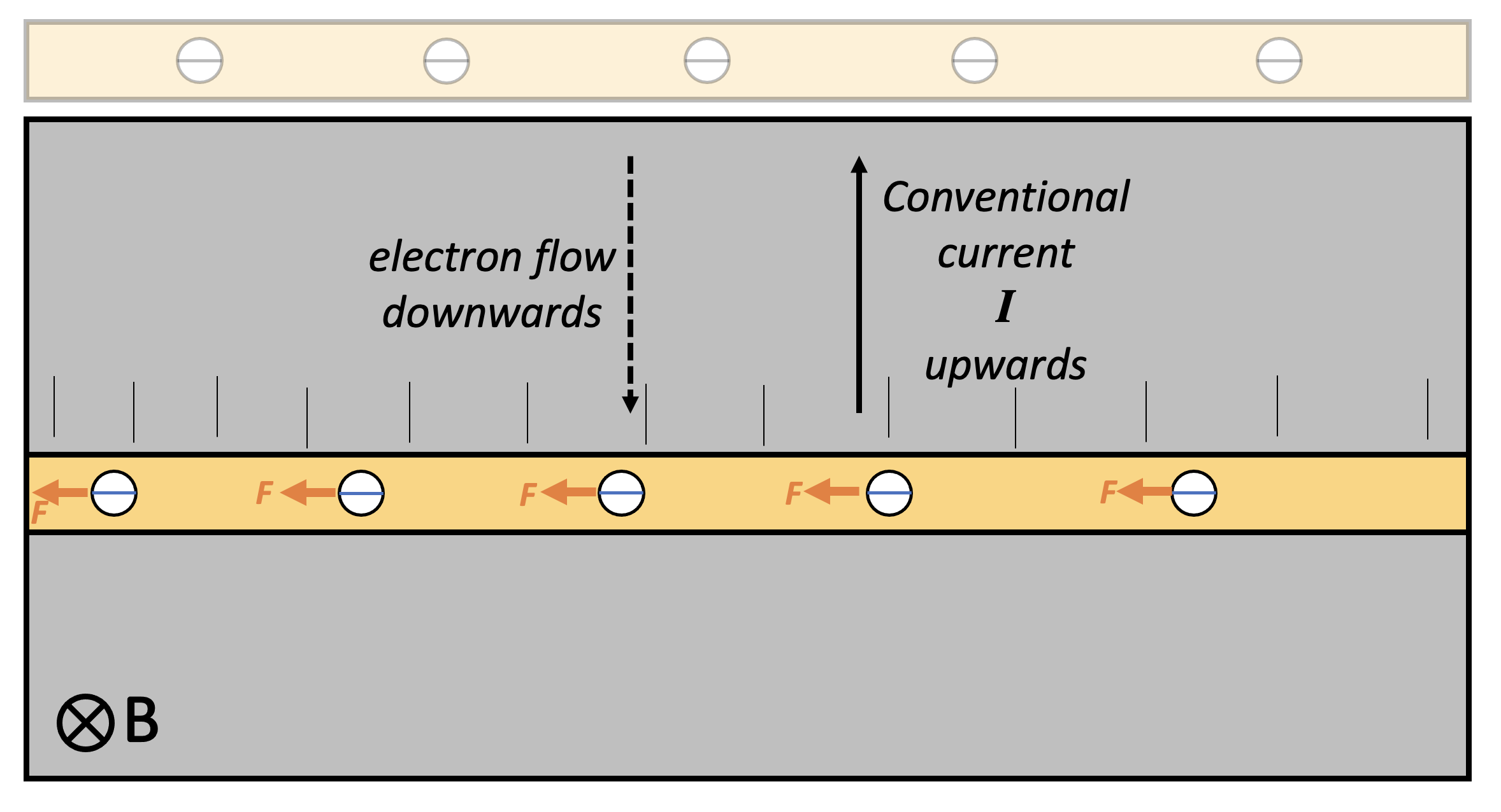
The copper conductor contains many free conduction electrons. When the conductor is moved sharply downwards, the electrons are carried downwards as well. In effect, the downward moving conductor can be thought of as a flow of charge; or, more to the point, as an electrical current. However, since electrons are negatively charged, this downward flow of negative charge is equivalent to an upward flow of positive charge. That is to say, the conventional current direction on this diagram is upwards.
Applying Fleming Left Hand Rule (FLHR) to this instance, we find that each electron experiences a small force tugging it to the left — but only while the conductor is being moved downwards.
This results in the left hand side of the conductor becoming negatively charged and the right hand side becoming positively charged: in short, a potential difference builds up across the conductor. This potential difference only happens when the conductor is moving through the magnetic field in such a way that the electrons are tugged towards one end of the conductor. (There is, of course, the Hall Effect in some other instances, but we won’t go into that here.)
As soon as the conductor stops moving, the potential difference is no longer induced as there is no ‘charge flow’ through the magnetic field and, hence, no current and no FLHR motor effect force acting on the electrons.
Faraday’s model of electromagnetic induction
Michael Faraday (1791-1867) discovered the phenomenon of electromagnetic induction in 1831 and explained it using the idea of a conductor cutting magnetic field lines. This is an immensely valuable model which not only explains EMI but can also generate quantitative predictions and, yes, it should definitely be taught to students — but perhaps the approach outlined above is better to introduce EMI to students.
The left hand rule not knowing what the right hand rule is doing . . .
We usually apply Fleming’s Right Hand Rule (FRHW) to cases of EMI, Can we replace its use with FLHR? Perhaps, if you wanted to. However, FRHR is a more direct and straightforward shortcut to predicting the direction of conventional current in this type of situation.
Students find learning about electric motors difficult because:
They find it hard to predict the direction of the force produced on a conductor in a magnetic field, either with or without Fleming’s Left Hand Rule.
They find it hard to understand how a split ring commutator works.
In this post, I want to focus on a suggested teaching sequence for the action of a split ring commutator, since I’ve covered the first point in previous posts.
Who needs a ‘split ring commutator’ anyway?
We all do, if we are going to build electric motors that produce a continuous turning motion.
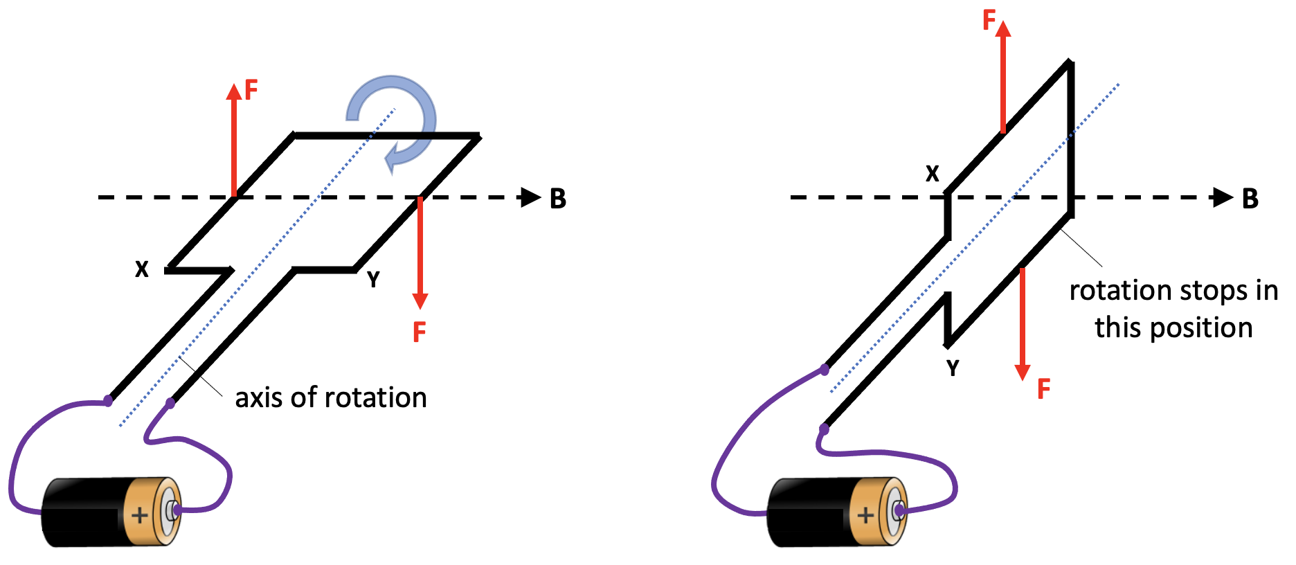
If we naively connected the ends of a coil to power supply, then the coil would make a partial turn and then lock in place, as shown below. When the coil is in the vertical position, then neither of the Fleming’s Left Hand Rule (FLHR) forces will produce a turning moment around the axis of rotation.
When the coil moves into this vertical position, two things would need to happen in order to keep the coil rotating continuously in the same direction.
The current to the coil needs to be stopped at this point, because the FLHR forces acting at this moment would tend to hold the coil stationary in a vertical position. If the current was cut at this time, then the momentum of the moving coil would tend to keep it moving past this ‘sticking point’.
The direction of the current needs to be reversed at this point so that we get a downward FLHR force acting on side X and an upward FLHR force acting on side Y. This combination of forces would keep the coil rotating clockwise.
This sounds like a tall order, but a little device known as a split ring commutator can help here.
One (split) ring to rotate them all
The word commutator shares the same root as commute and comes from the Latin commutare (‘com-‘ = all and ‘-mutare‘ = change) and essentially means ‘everything changes’. In the 1840s it was adopted as the name for an apparatus that ‘reverses the direction of electrical current from a battery without changing the arrangement of the conductors’.
In the context of this post, commutator refers to a rotary switch that periodically reverses the current between the coil and the external circuit. This rotary switch takes the form of a conductive ring with two gaps: hence split ring.
Tracking the rotation of a coil through a whole rotation
In this picture below, we show the coil connected to a dc power supply via two ‘brushes’ which rest against the split ring commutator (SRC). Current is flowing towards us through side X of the coil and away from us through side Y of the coil (as shown by the dot and cross 2D version of the diagram. This produces an upward FLHR force on side X and a downward FLHR force on side Y which makes the coil rotate clockwise.
Now let’s look at the coil when it has turned 45 degrees. We note that the SRC has also turned by 45 degrees. However, it is still in contact with the brushes that supply the current. The forces on side X and side Y are as noted before so the coil continues to turn clockwise.
Next, we look at the situation when the coil has turned by another 45 degrees. The coil is now in a vertical position. However, we see that the gaps in the SRC are now opposite the brushes. This means that no current is being supplied to the coil at this point, so there are no FLHR forces acting on sides X and side Y. The coil is free to continue rotating clockwise because of momentum.
Let’s now look at the situation when the coil has rotated a further 45 degrees to the orientation shown below. Note that the side of the SRC connected to X is now touching the brush connected to the positive side of the power supply. This means that current is now flowing away from us through side X (whereas previously it was flowing towards us). The current has reversed direction. This creates a downward FLHR force on side X and an upward FLHR force on side Y (since the current in Y has also reversed direction).
And a short time later when the coil has moved a total of180 degrees from its starting point, we can observe:
And later:
And later still:
And then:
And then eventually we get back to:
Summary
In short, a split ring commutator is a rotary switch in a dc electric motor that reverses the current direction through the coil each half turn to keep it rotating continuously.
I hope that this teaching sequence will allow more students to be comfortable with the concept of a split ring commutator — anything that results in a fewer split ring commuHATERS would be a win for me 😉
He knew all the tricks: dramatic irony, metaphor, pathos, puns, parody, litotes* and . . . satire. He was vicious.
Monty Python, The Tale of the Pirhana Brothers
As we all know, students really struggle with questions in science exams which require answers written ‘at paragraph length’ (dread words!). What follows are some tips that I have found useful when coaching students to improve performance.
Many teachers of English enjoy great success with acronyms such as PEEL (Point. Example. Explain. Link). However, I think these have limited applicability in Science as the required output of extended writing questions (EWQs) varies too much for even a loose one-size-fits-all approach.
What I encourage students to do is:
1. Write in bullet points
The bullet points (BPs) should be short but fully grammatical sentences (and not single words or part sentences).
The reason for this is twofold:
Focus: it stops an attempted answer spiralling out of control. Without organising my answer using BPs, I find myself running out of space. I start with the best of intentions but realise, as I fill in the last remaining line of the allocated space, that I haven’t reached the end of the first sentence yet!!!
Organisation: it discourages students from repeating the same thing again and again. I have sometimes marked extended writing answers that repeat the same point multiple times. Yes, they have filled the space and yes, they have written in complete sentences. But there is no additional information except the first section rewritten using different words!
2. Use correct scientific vocabulary
Students often make the incorrect assumption that ‘Explain‘ means ‘Explain to a non-specialist using jargon-free everyday language‘.
In fact nothing could be further from the truth. The expectation of EWQs in general is that students should be able to communicate to a scientist-peer using technical language appropriate for GCSE or A-level.
Partly, this misconception is our own fault. When students ask for an explanation from their teachers, we often — with the best of intentions! — try to express it in non-threatening, jargon-free language.
This is the model that many students follow when responding to EWQs. For example, I remember groaning in frustration when marking an A-level Physics script where the student has repeatedly written the word ‘move’ when the terms ‘accelerate’ or ‘constant velocity’ would have communicated her understanding with far more clarity.
In Science, what is often derided as ‘jargon’ isn’t an actual barrier to understanding. In truth, a shared, specialist language is an essential pathway to concision and clarity and a guard-rail against inadvertent miscommunication.
3. Write as many BPs as there are marks
For example, students should aim to write 3 BPs in response to a 3-mark EWQ.
4. Read all your BPs. Taken as a whole — do they *answer* the damn question?
If yes, move on. If no, then add another BP.
Part two: modelling the EWQ response-process
‘What does “quantum” mean, anyway?’
‘It means “add another nought.”‘
Terry Pratchett, Pyramids
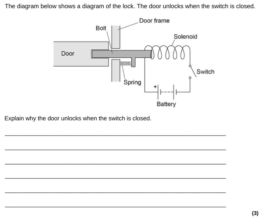
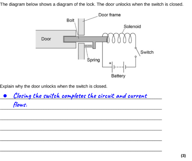
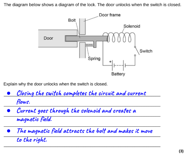
This EWQ has 3 marks, so we should aim for 3 BPs.
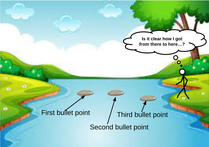
I use the analogy of crossing a river using stepping stones. One stepping stone won’t be enough but three will let us get across — hopefully without us getting our feet wet.
Let’s write our first BP. I suggest that students begin by stating what they may think is obvious.
Next, we think about what we could write as our second BP. But — and this is essential! — we consider it from the vantage point of our first BP.
Our second BP is the next-most-obvious-BP: what happens to the solenoid when an electric current goes through it? Remember that we are supposed to use technical language, so we will call a solenoid a solenoid, so to speak.
Next, we consider what to write for our third (and maybe final) BP. Again, we should be thinking of this from the viewpoint of what we have already written.
Finally, and this point is not to be missed, we should look back at all the BPs we have written and ask ourselves the all-important ‘Have I actually answered the question that was asked originally?‘
In this case, the answer is YES, we have explained why the door unlocks when the switch is closed.
This means that we can stop here and move on to the next question.
*Litotes (LIE-tote-ees): an ironic understatement in which an affirmative is expressed as a negative e.g. I won’t be sorry to get to the end of this not-at-all-overlong blog post.
Students undoubtedly find electromagnetism tricky, especially at GCSE.
I have found it helpful to start with the F = BIl formula.
Introducing the “magnetic Bill” formula
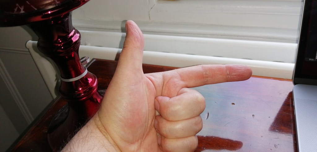
This means that we can use the streamlined F-B-I mnemonic — developed by no less a personage than Robert J. Van De Graaff (1901-1967) of Van De Graaff generator fame — instead of the cumbersome “First finger = Field, seCond finger = Current, thuMb = Motion” convention.
Say F, then B, then I ….
Students find the beginning steps of applying Fleming’s Left Hand Rule (FLHR) quite hard to apply, so I print out little 3D “signposts” to help them. You can download file by clicking the link below.
Important tip: it can be really helpful if students label the arrows on both sides, such as in the example shown below. (The required precision in double sided printing defeated me!)
Another example of the FLHR signpost in use
Signposts for Fleming’s Right Hand Rule are included on the template.
‘Transformers’ is one of the trickier topics to teach for GCSE Physics and GCSE Combined Science.
I am not going to dive into the scientific principles underlying electromagnetic induction here (although you could read this post if you wanted to), but just give a brief overview suitable for a GCSE-level understanding of:
The basic principle of a transformer; and
How step down and step up transformers work.
One of the PowerPoints I have used for teaching transformers is here. This is best viewed in presenter mode to access the animations.
The basic principle of a transformer
A GIF showing the basic principle of a transformer. (BTW This can be copied and pasted into a presentation if you wish,)
The primary and secondary coils of a transformer are electrically isolated from each other. There is no charge flow between them.
The coils are also electrically isolated from the core that links them. The material of the core — iron — is chosen not for its electrical properties but rather for its magnetic properties. Iron is roughly 100 times more permeable (or transparent) to magnetic fields than air.
The coils of a transformer are linked, but they are linked magnetically rather than electrically. This is most noticeable when alternating current is supplied to the primary coil (green on the diagram above).
The current flowing in the primary coil sets up a magnetic field as shown by the purple lines on the diagram. Since the current is an alternating current it periodically changes size and direction 50 times per second (in the UK at least; other countries may use different frequencies). This means that the magnetic field also changes size and direction at a frequency of 50 hertz.
The magnetic field lines from the primary coil periodically intersect the secondary coil (red on the diagram). This changes the magnetic flux through the secondary coil and produces an alternating potential difference across its ends. This effect is called electromagnetic induction and was discovered by Michael Faraday in 1831.
Energy is transmitted — magnetically, not electrically — from the primary coil to the secondary coil.
As a matter of fact, a transformer core is carefully engineered so to limit the flow of electrical current. The changing magnetic field can induce circular patterns of current flow (called eddy currents) within the material of the core. These are usually bad news as they heat up the core and make the transformer less efficient. (Eddy currents are good news, however, when they are created in the base of a saucepan on an induction hob.)
Stepping Down
One of the great things about transformers is that they can transform any alternating potential difference. For example, a step down transformer will reduce the potential difference.
A GIF showing the basic principle of a step down transformer. (BTW This can be copied and pasted into a presentation if you wish,)
The secondary coil (red) has half the number of turns of the primary coil (green). This halves the amount of electromagnetic induction happening which produces a reduced output voltage: you put in 10 V but get out 5 V.
And why would you want to do this? One reason might be to step down the potential difference to a safer level. The output potential difference can be adjusted by altering the ratio of secondary turns to primary turns.
One other reason might be to boost the current output: for a perfectly efficient transformer (a reasonable assumption as their efficiencies are typically 90% or better) the output power will equal the input power. We can calculate this using the familiar P=VI formula (you can call this the ‘pervy equation’ if you wish to make it more memorable for your students).
Thus: Vp Ip = Vs Is so if Vs is reduced then Is must be increased. This is a consequence of the Principle of Conservation of Energy.
Stepping up
A GIF showing the basic principle of a step up transformer. (BTW This can be copied and pasted into a presentation if you wish,)
There are more turns on the secondary coil (red) than the primary (green) for a step up transformer. This means that there is an increased amount of electromagnetic induction at the secondary leading to an increased output potential difference.
Remember that the universe rarely gives us something for nothing as a result of that damned inconvenient Principle of Conservation of Energy. Since Vp Ip = Vs Is so if the output Vs is increased then Is must be reduced.
If the potential difference is stepped up then the current is stepped down, and vice versa.
Last nail in the coffin of the formula triangle…
Although many have tried, you cannot construct a formula triangle to help students with transformer calculations.
Now is your chance to introduce students to a far more sensible and versatile procedure like FIFA (more details on the PowerPoint linked to above)
Aristotle memorably said that Nature abhors a vacuum: in other words. he thought that a region of space entirely devoid of matter, including air, was logically impossible.
Aristotle turned out to be wrong in that regard, as he was in numerous others (but not quite as many as we – secure and perhaps a little complacent and arrogant as we look down our noses at him from our modern scientific perspective – often like to pretend).
An amusing version which is perhaps more consistent with our current scientific understanding was penned by D. J. Griffiths (2013) when he wrote: Nature abhors a change in flux.
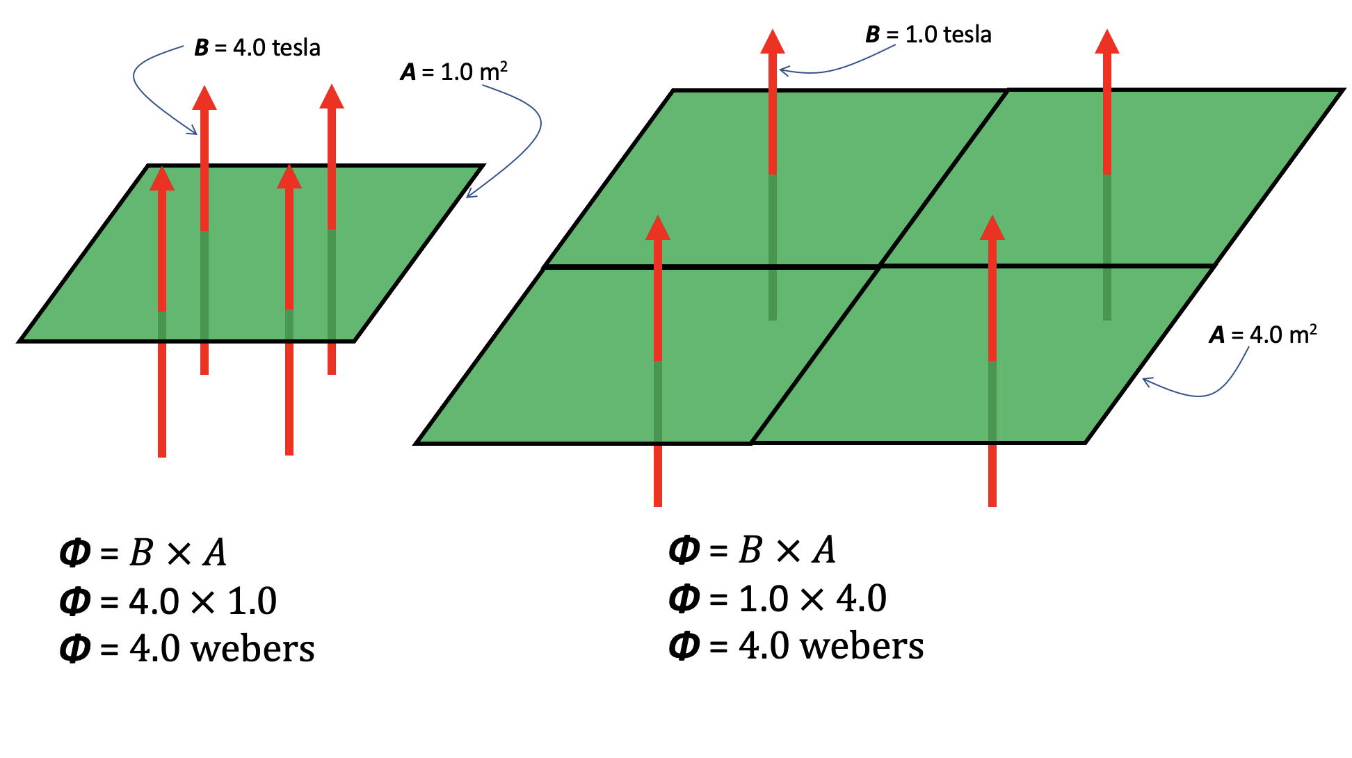
Magnetic flux (represented by the Greek letter phi, Φ) is a useful quantity that takes account of both the strength of the magnetic field and its extent. It is the total ‘magnetic flow’ passing through a given area. You can also think of it as the number of magnetic field lines multiplied by the area they pass through so a strong magnetic field confined to a small area might have the same flux (or ‘effect’) as weaker field spread out over a large area.
Lenz’s Law
Emil Lenz formulated an earlier statement of the Nature abhors a change of flux principle when he stated what I think is the most consistently underrated laws of electromagnetism, at least in terms of developing students’ understanding:
The current induced in a circuit due to a change in a magnetic field is directed to oppose the change in flux and to exert a mechanical force which opposes the motion.
Lenz’s Law (1834)
This is a qualitative rather than a quantitive law since it is about the direction, not the magnitude, of an induced current. Let’s look at its application in the familiar A-level Physics context of dropping a bar magnet through a coil of wire.
Dropping a magnet through a coil in pictures
Picture 1
In picture 1 above, the magnet is approaching the coil with a small velocity v. The magnet is too far away from the coil to produce any magnetic flux in the centre of the coil. (For more on the handy convention I have used to draw the coils and show the current flow, please click on this link.) Since there is no magnetic flux, or more to the point, no change in magnetic flux, then by Faraday’s Law of Electromagnetic Induction there is no induced current in the coil.
Picture 2
in picture 2, the magnet has accelerated to a higher velocity v due to the effect of gravitational force. The magnet is now close enough so that it produces a magnetic flux inside the coil. More to the point, there is an increase in the magnetic flux as the magnet gets closer to the coil: by Faraday’s Law, this produces an induced current in the coil (shown using the dot and cross convention).
To ascertain the direction of the current flow in the coil we can use Lenz’s Law which states that the current will flow in such a way so as to oppose the change in flux producing it. The red circles show the magnetic field lines produced by the induced current. These are in the opposite direction to the purple field lines produced by the bar magnet (highlighted yellow on diagram 2): in effect, they are attempting to cancel out the magnetic flux which produce them!
The direction of current flow in the coil will produce a temporary north magnetic pole at the top of the coil which, of course, will attempt to repel the falling magnet; this is ‘mechanical force which opposes the motion’ mentioned in Lenz’s Law. The upward magnetic force on the falling magnet will make it accelerate downward at a rate less than g as it approaches the coil.
Picture 3
In picture 3, the purple magnetic field lines within the volume of the coil are approximately parallel so that there will be no change of flux while the magnet is in this approximate position. In other words, the number of field lines passing through the cross-sectional area of the coil will be approximately constant. Using Faraday’s Law, there will be no flow of induced current. Since there is no change in flux to oppose, Lenz’s Law does not apply. The magnet will be accelerating downwards at g.
Picture 4
As the magnet emerges from the bottom of the coil, the magnetic flux through the coil decreases. This results in a flow of induced current as per Faraday’s Law. The direction of induced current flow will be as shown so that the red field lines are in the same direction as the purple field lines; Lenz’s Law is now working to oppose the reduction of magnetic flux through the coil!
A temporary north magnetic pole is generated by the induced current at the lower end of the coil. This will produce an upward magnetic force on the falling magnet so that it accelerates downward at a rate less than g. This, again, is the ‘mechanical force which opposes the motion’ mentioned in Lenz’s Law.
Dropping a magnet through a coil in graphical form
This would be one of my desert island graphs since it is such a powerfully concise summary of some beautiful physics.
The graph shows the reversal in the direction of the current as discussed above. Also, the maximum induced emf in region 2 (blue line) is less than that in region 4 (red line) since the magnet is moving more slowly.
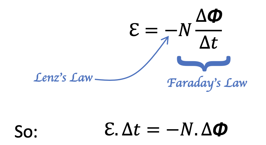
What is more, from Faraday’s Law (where ℇ is the induced emf and N is total number of turns of the coil), the blue area is equal to the red area since:
and N and ∆Φ are fixed values for a given coil and bar magnet.
As I said previously, there is so much fascinating physics in this graph that I think it worth exploring in depth with your A level Physics students 🙂
Other news
If you have enjoyed this post, then you may be interested to know that I’ve written a book! Cracking Key Concepts in Secondary Science (co-authored with Adam Boxer and Heena Dave) is due to be published by Corwin in July 2021.
References
Lenz, E. (1834), “Ueber die Bestimmung der Richtung der durch elektodynamische Vertheilung erregten galvanischen Ströme”, Annalen der Physik und Chemie, 107 (31), pp. 483–494
Griffiths, David (2013). Introduction to Electrodynamics. p. 315.
A solenoid is an electromagnet made of a wire in the form of a spiral whose length is larger than its diameter.
A solenoid
The word solenoid literally means ‘pipe-thing‘ since it comes from the Greek word ‘solen‘ for ‘pipe’ and ‘-oid‘ for ‘thing’.
An alternate universe version of the Troggs’ famous 1966 hit record
And they are such an all-embracingly useful bit of kit that one might imagine an alternate universe where The Troggs might have sang:
Pipe-thing! You make my heart sing!
You make everything groovy, pipe-thing!
And pipe-things do indeed make everything groovy: solenoids are at the heart of the magnetic pickups that capture the magnificent guitar riffs of The Troggs at their finest.
The Butterfly Field
Very few minerals are naturally magnetised. Lodestones are pieces of the ore magnetite that can attract iron. (The origin of the name is probably not what you think — it’s named after the region, Magnesia, where it was first found). In ancient times, lodestones were so rare and precious that they were worth more than their weight in gold.
Over many centuries, by patient trial-and-error, humans learned how to magnetise a piece of iron to make a permanent magnet. Permanent magnets now became as cheap as chips.
A permanent bar magnet is wrapped in an invisible evanescent magnetic field that, given sufficient poetic license, can remind one of the soft gossamery wings of a butterfly…
Orient a bar magnet vertically so that students can see the ‘butterfly field’ analogy…
The field lines seem to begin at the north pole and end at the south pole. ‘Seem to’ because magnetic field lines always form closed loops.
This is a consequence of Maxwell’s second equation of Electromagnetism (one of a system of four equations developed by James Clark Maxwell in 1873 that summarise our current understanding of electromagnetism).
Using the elegant differential notation, Maxwell’s second equation is written like this:
Maxwell’s second equation of electromagnetism.
It could be read aloud as ‘del dot B equals zero’ where B is the magnetic field and del (the inverted delta symbol) does not represent a quantity but is the differential operator which describes how the field lines curl in three dimensional space.
This also tells us that magnetic monopoles (that is to say, isolated N and S poles) are impossible. A north-seeking pole is always paired with a south-seeking pole.
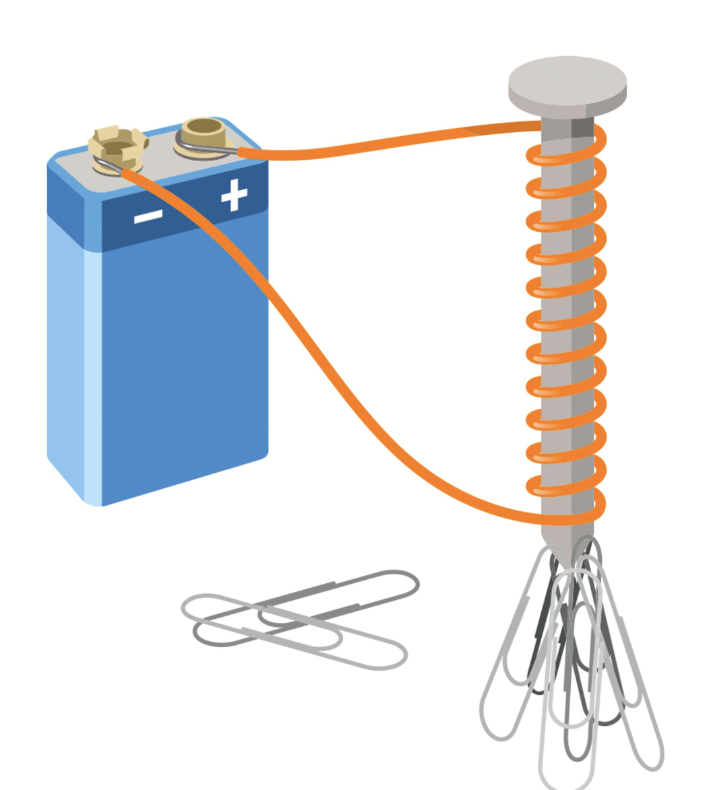
Magnetising a solenoid
A current-carrying coil will create a magnetic field as shown below.
The magnetic field of a solenoid.(Note that the field lines in the centre are truncated to save space, but would form very large loops as mentioned above.)
The wire is usually insulated (often with a tough, transparent and nearly invisible enamel coating for commercial solenoids), but doesn’t have to be. Insulation prevents annoying ‘short circuits’ if the coils touch. At first sight, we see the familiar ‘butterfly field’ pattern, but we also see a very intense magnetic field in the centre of the solenoid,
For a typical air-cored solenoid used in a school laboratory carrying one ampere of current, the magnetic field in the centre would have a strength of about 84 microtesla. This is of the same order as the Earth’s magnetic field (which has a typical value of about 50 microtesla). This is just strong enough to deflect the needle of a magnetic compass placed a few centimetres away and (probably) make iron filings align to show the magnetic field pattern around the solenoid, but not strong enough to attract even a small steel paper clip. For reference, the strength of a typical school bar magnet is about 10 000 microtesla, so our solenoid is over one hundred times weaker than a bar magnet.
However, we can ‘boost’ the magnetic field by adding an iron core. The relative permeability of a material is a measurement of how ‘transparent’ it is to magnetic field lines. The relative permeability of pure iron is about 1500 (no units since it’s relative permeability and we are comparing its magnetic properties with that of empty space). However, the core material used in the school laboratory is more likely to be steel rather than iron, which has a much more modest relative permeability of 100.
So placing a steel nail in the centre of a solenoid boosts its magnetic field strength by a factor of 100 — which would make the solenoid roughly as strong as a typical bar magnet.
But which end is north…?
The N and S-poles of a solenoid can change depending on the direction of current flow and the geometry of the loops.
The typical methods used to identify the N and S poles are shown below.
Methods of locating N and S pole of a solenoid that you should NOT use…
To go in reverse order for no particular reason, I don’t like using the second method because it involves a tricky mental rotation of the plane of view by 90 degrees to imagine the current direction as viewed when looking directly at the ends of the magnet. Most students, understandably in my opinion, find this hard.
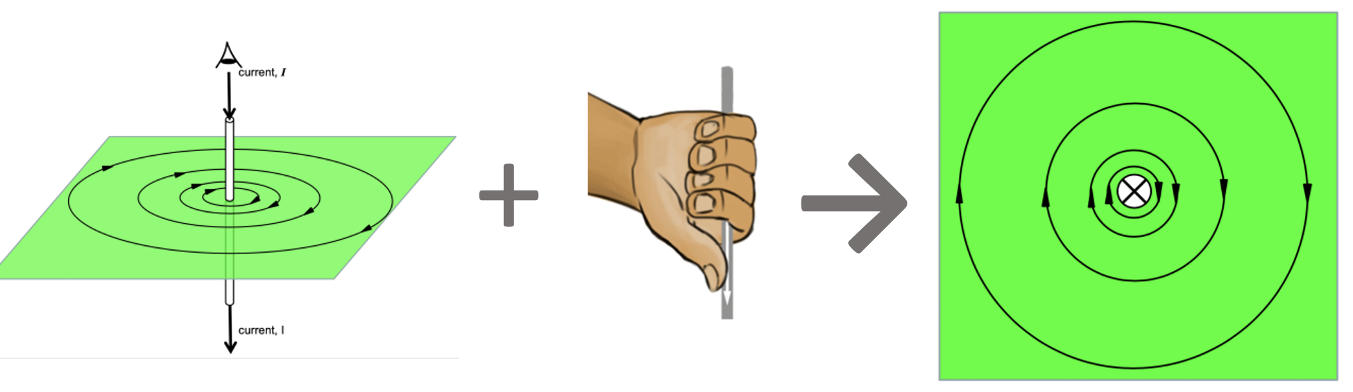
The first method I dislike because it creates confusion with the ‘proper’ right hand grip rule which tells us the direction of the magnetic field lines around a long straight conductor and which I’ve written about before . . .
The right hand grip rule illustrated: the field line curl in the same direction as the finger when the thumb is pointed in the direction of the current.
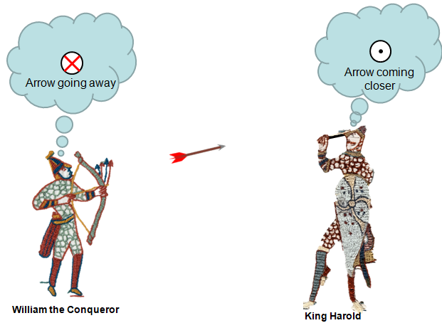
The direction of the current in the last diagram is shown using the ‘dot and cross’ convention which, by a strange coincidence, I have also written about before . . .
If King Harold had been more familiar with the dot and cross notation, history could have turned out very differently…
How a solenoid ‘makes’ its magnetic field . . .
To begin the analysis we imagine the solenoid cut in half: what biologists would call a longitudinal section. Then we show the current directions of each element using the dot and cross convention. Then we consider just two elements, say A and B as shown below.
Continuing this analysis below:
The region inside the solenoid has a very strong and nearly uniform magnetic field. By ‘uniform’ we mean that the field lines are nearly straight and equally spaced meaning that the magnetic field has the same strength at any point.
The region outside the solenoid has a magnetic field which gradually weakens as you move away from the solenoid (indicated by the increased spacing between the field lines); its shape is also nearly identical to the ‘butterfly field’ of a bar magnet as mentioned above.
Since the field lines are emerging from X, we can confidently assert that this is a north-seeking pole, while Y is a south-seeking pole.
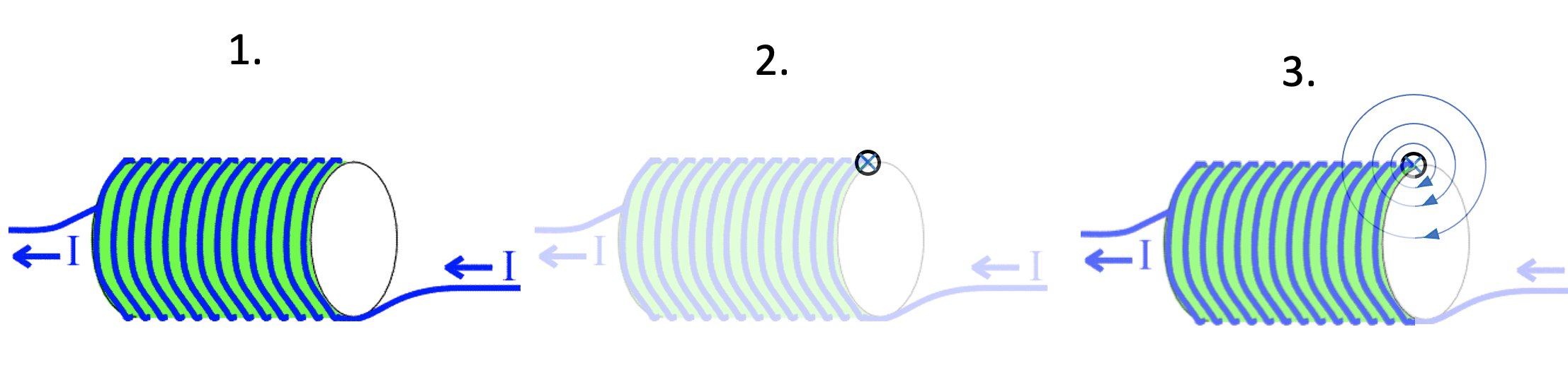
Which end is north, using only the ‘proper’ right hand grip rule…
First, look very carefully at the geometry of current flow (1).
Secondly, isolate one current element, such as the one shown in picture (2) above.
Thirdly, establish the direction of the field lines using the standard right hand grip rule (3).
Since the field lines are heading into this end of the solenoid, we can conclude that the right hand side of this solenoid is, in fact, a south-seeking pole.
In my opinion, this is easier and more reliable than using any of the other alternative methods. I hope that readers that have read this far will (eventually) come to agree.
Has a school physics experiment or demonstration ever changed the course of human history?
On 21 April 1820, one such demonstration most definitely did. According to physics lore, Hans Christian Øersted was attempting to demonstrate to his students that, according to the scientific understanding of the day, there was in fact no connection between magnetism and electricity.
To this laudable end, he placed a compass needle near to a wire to show that when the current was switched on, the needle would not be affected.
Except that it was affected. Frequently. Each and every time Øersted switched on the electric current, the needle was deflected from pointing North.
Everybody has heard that wise old saw that ‘If it doesn’t work, it’s physics…” except that in this case ‘It did actually work as it was supposed to but in an unexpected way due to a hitherto-unknown-completely-new-branch-of-physics.’
Øersted, to his eternal credit, did not let it lie there and was a pioneer of the new science of electromagnetism.
Push-me-pull-you: or, two current-carrying conductors
One curious consequence of Øersted’s new science was the realisation that, since electric currents create magnetic fields, two wires carrying electric currents will exert a force on each other.
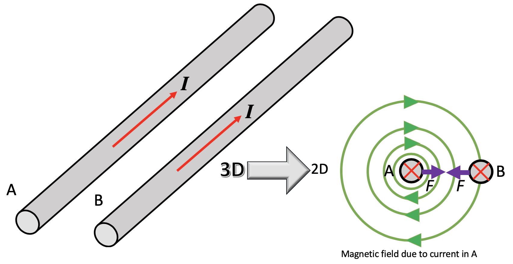
Let’s consider two long, straight conductors placed parallel to each other as shown.
In the diagram above, the magnetic field produced by the current in A is shown by the green lines. Applying Fleming’s Left Hand Rule* to conductor B, we find that a force is produced on B which acts towards conductor A. We could go through a similar process to find the force acting on B, but it’s far easier to apply Newton’s Third Law instead: if body A exerts a force on body B, then body B exerts an equal and opposite force on body A. Hence, conductor A experiences a force which pulls it towards conductor B.
So, two long, straight conductors carrying currents in the same direction will be attracted to each other. By a similar analysis, we find that two long, straight conductors carrying currents in opposite directions will be repelled from each other.
In the past, this phenomenon was used to define the ampere as the unit of current: ‘The ampere is that constant current which, if maintained in two straight parallel conductors of infinite length, of negligible circular cross-section, and placed 1 m apart in vacuum, would produce between these conductors a force equal to 2×10⁻⁷ newton per metre of length.‘ However, the 2019 redefinition of the SI system has ditched this and adopted a new definition in terms of the transfer of the elementary charge, e.
Enter Albert Einstein, pursuing an enigma
What is the connection between magnetism and electricity? It was precisely this puzzle that started Albert Einstein on the road to special relativity. It is one of the unsung triumphs of this theory that it lays bare the connection between magnetism and electricity.
In what follows, we’re going to apply Einstein’s analysis to the situation of two long, straight current-carrying conductors. Acknowledgment: I’m going to following a line of argument laid out in Beiser 1988: 19-22.
It’s gotta be perfect (or ‘idealised’, if you prefer)
Let’s consider two idealised conductors A and B both at rest in the inertial reference frame of the laboratory. The flow of charge in both conductors is made up of positive and negative charge carriers moving in opposite directions with a speed v.
None of the charges in A interact with the other charges in A because we are considering an idealised conductor. However, the charges in A will interact with the charges in B.
Two conductors viewed from the inertial frame of the laboratory
Flip the inertial reference frame
Now let’s look at the situation from the inertial reference frame of one of the positive charges in A. For simplicity, we can focus on a single positive charge in A since it does not interact with any of the other charges in A.
With reference to this inertial frame, the positive charge in A is stationary and the positive charges in B are also stationary.
However, the inertial frame of the laboratory is moving right-to-left with a speed v and the negative charges are moving right-to-left with a speed of 2v.
The same two conductors viewed from the inertial frame of one of the positive charges in conductor A. Note that all the positive charges are now stationary; the laboratory is moving with speed v right to left, and the negative charges are moving with speed 2v right to left
Since the positive charges in B are stationary with respect to the positive charge in A, the distance between them is the same as it was in the laboratory inertial frame. However, since the negative charges in B are moving with speed 2v with respect to positive charge in A, the spacing between is contracted due to relativistic length contraction (see Lottie and Lorentzian Length Contraction).
Because of this, the negative charge density of B increases since they are closer together. However, the positive charge density of B remains the same since they are stationary relative to the positive charge in A so there is no length contraction.
This means that, as far as the positive charge in A is concerned, conductor B has a net negative charge which means the positive charge experiences an attractive Coulomb’s Law electrical force towards B.
A similar analysis applied to electric currents in opposite directions would show that the positive charge in A would experience a repulsive Coulomb’s Law electrical force. The spacing between the positive charges in B would be contracted but the spacing between the negative charges remains unchanged, so conductor B has a net positive charge because the positive charge density has increased but the negative charge density is unchanged.
Magnetism? THERE IS NO MAGNETISM!!!!
So what we normally think of as a ‘magnetic’ force in the inertial frame of the laboratory can be explained as a consequence of special relativity altering the charge densities in conductors. Although we have just considered a special case, all magnetic phenomena can be interpreted on the basis of Coulomb’s Law, charge invariance** and special relativity.
For the interested reader, Duffin (1980: 388-390) offers a quantitative analysis where he uses a similar argument to derive the expression for the magnetic field due to a long straight conductor.
** ‘A current-carrying conductor that is electrically neutral in one frame of reference might not be neutral in another frame. How can this observation be reconciled with charge invariance? The answer is that we must consider the entire circuit of which the conductor is a part. Because a circuit must be closed for a current to occur in it, for every current element in one direction that a moving observer find to have, say, a positive charge, there must be another current element in the opposite direction which the same observer finds to have a negative charge. Hence, magnetic forces always act between different parts of the same circuit, even though the circuit as a whole appears electrically neutral to all observers.’ Beiser 1988: 21
Beiser, A. (1988). Concepts of modern physics. Tata McGraw-Hill Education
Duffin, W. J. (1980). Electricity and magnetism. McGraw-Hill.


:format(jpeg):mode_rgb():quality(40)/discogs-images/R-7900735-1451266037-4913.jpeg.jpg)