Electromagnetic induction — using the LEFT hand rule…?

They do observe I grow to infinite purchase,
The left hand way;

John Webster, The Duchess of Malfi

Electromagnetic induction — the fact that moving a conductor inside a magnetic field in a certain direction will generate (or induce) a potential difference across its ends — is one of those rare-in-everyday-life phenomena that students very likely will never have come across before. In their experience, potential differences have heretofore been produced by chemical cells or by power supply units that have to be plugged into the mains supply. Because of this, many of them struggle to integrate electromagnetic induction (EMI) into their physical schema. It just seems such a random, free floating and unconnected fact.

What follows is a suggested teaching sequence that can help GCSE-level students accept the physical reality of EMI without outraging their physical intuition or appealing to a sketchily-explained idea of ‘cutting the field lines’.

‘Look, Ma! No electrical cell!’

I think it is immensely helpful for students to see a real example of EMI in the school laboratory, using something like the arrangement shown below.

A length of copper wire used to cut the magnetic field between two Magnadur magnets on a yoke will induce (generate) a small potential difference of about 5 millivolts. What is particularly noteworthy about doing this as a class experiment is how many students ask ‘How can there be a potential difference without a cell or a power supply?’

The point of this experiment is that in this instance the student is the power supply: the faster they plunge the wire between the magnets then the larger the potential difference that will be induced. Their kinetic energy store is being used to generate electrical power instead of the more usual chemical energy store of a cell.

But how to explain this to students?

A common option at this point is to start talking about the conductor cutting magnetic field lines: this is hugely valuable, but I recommend holding fire on this picture for now — at least for novice learners.

What I suggest is that we explain EMI in terms of a topic that students will have recently covered: the motor effect.

This has two big ‘wins’:

  • It gives a further opportunity for students to practice and apply their knowledge of the motor effect.
  • Students get the chance to explain an initially unknown phenomenon (EMI) in terms of better understood phenomenon (motor effect). The motor effect will hopefully act as the footing (to use a term from the construction industry) for their future understanding of EMI.

Explaining EMI using the motor effect

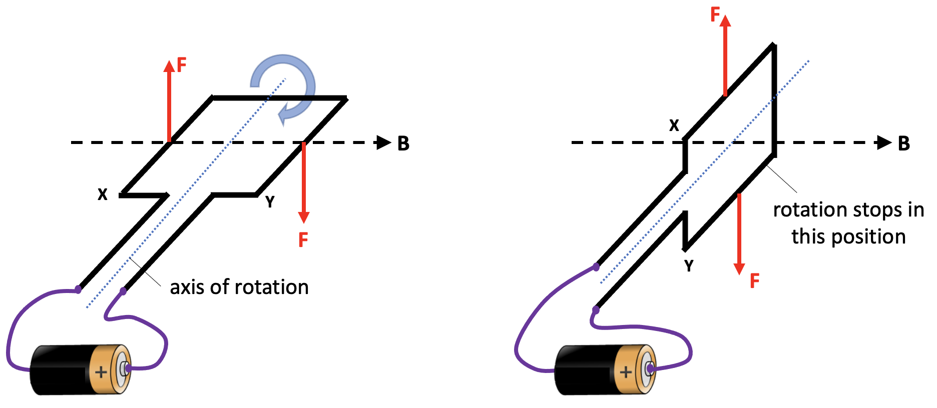
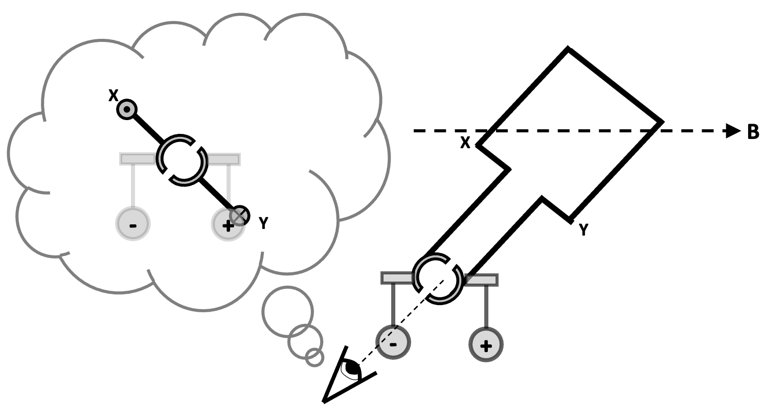
The copper conductor contains many free conduction electrons. When the conductor is moved sharply downwards, the electrons are carried downwards as well. In effect, the downward moving conductor can be thought of as a flow of charge; or, more to the point, as an electrical current. However, since electrons are negatively charged, this downward flow of negative charge is equivalent to an upward flow of positive charge. That is to say, the conventional current direction on this diagram is upwards.

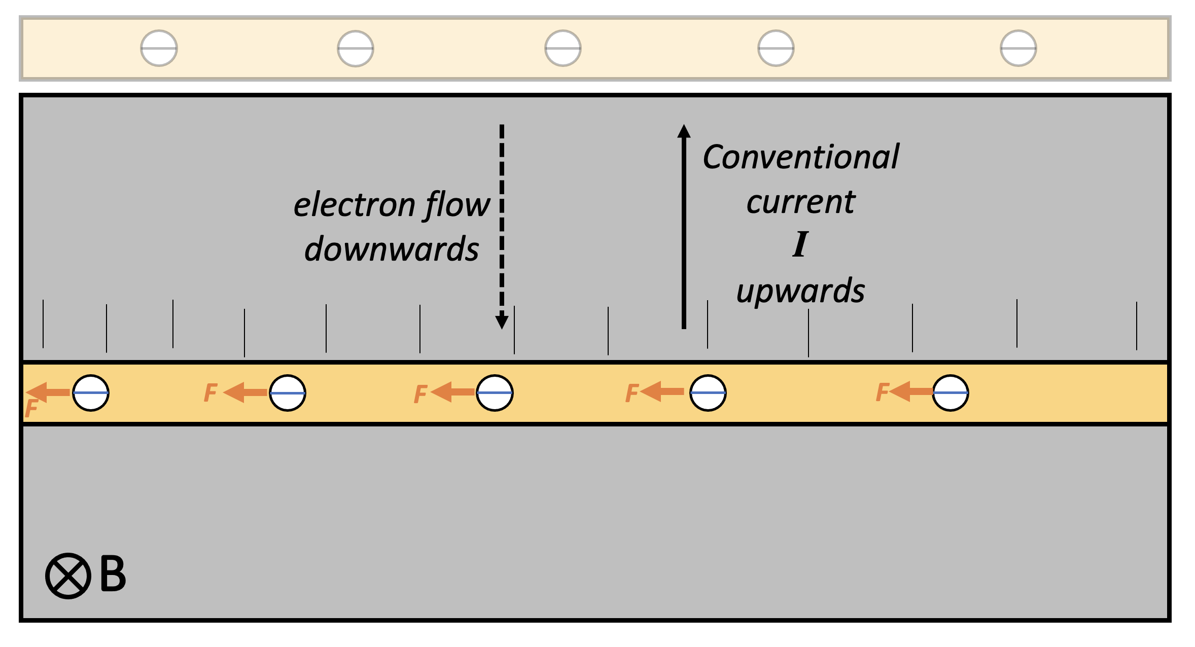
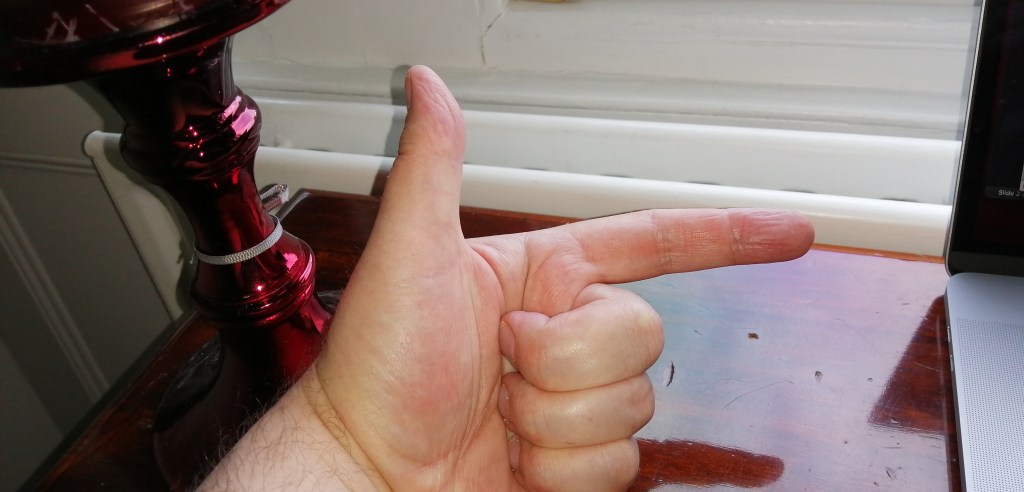
Applying Fleming Left Hand Rule (FLHR) to this instance, we find that each electron experiences a small force tugging it to the left — but only while the conductor is being moved downwards.

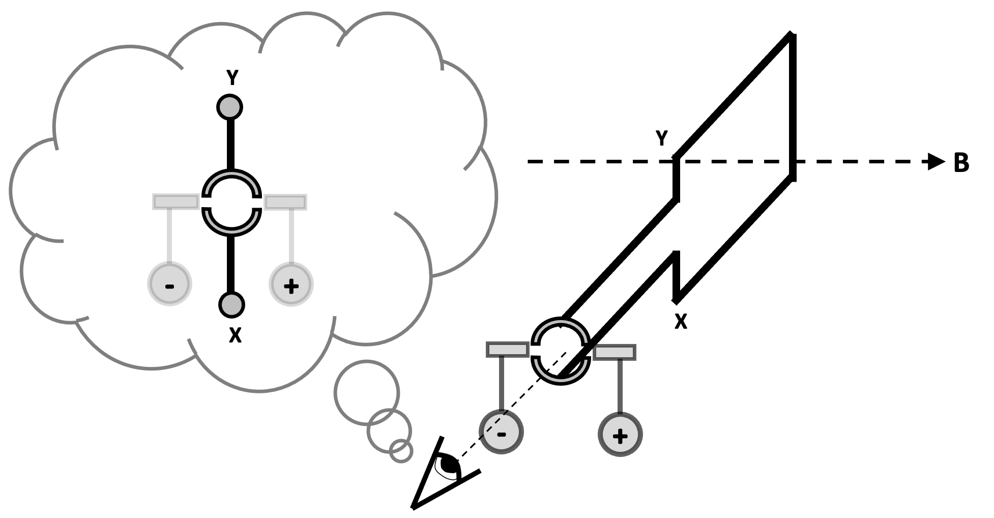
This results in the left hand side of the conductor becoming negatively charged and the right hand side becoming positively charged: in short, a potential difference builds up across the conductor. This potential difference only happens when the conductor is moving through the magnetic field in such a way that the electrons are tugged towards one end of the conductor. (There is, of course, the Hall Effect in some other instances, but we won’t go into that here.)

As soon as the conductor stops moving, the potential difference is no longer induced as there is no ‘charge flow’ through the magnetic field and, hence, no current and no FLHR motor effect force acting on the electrons.

Faraday’s model of electromagnetic induction

Michael Faraday (1791-1867) discovered the phenomenon of electromagnetic induction in 1831 and explained it using the idea of a conductor cutting magnetic field lines. This is an immensely valuable model which not only explains EMI but can also generate quantitative predictions and, yes, it should definitely be taught to students — but perhaps the approach outlined above is better to introduce EMI to students.

The left hand rule not knowing what the right hand rule is doing . . .

We usually apply Fleming’s Right Hand Rule (FRHW) to cases of EMI, Can we replace its use with FLHR? Perhaps, if you wanted to. However, FRHR is a more direct and straightforward shortcut to predicting the direction of conventional current in this type of situation.

Split ring commutator? More like split ring commuHATER!

Students find learning about electric motors difficult because:

  1. They find it hard to predict the direction of the force produced on a conductor in a magnetic field, either with or without Fleming’s Left Hand Rule.
  2. They find it hard to understand how a split ring commutator works.

In this post, I want to focus on a suggested teaching sequence for the action of a split ring commutator, since I’ve covered the first point in previous posts.

Who needs a ‘split ring commutator’ anyway?

We all do, if we are going to build electric motors that produce a continuous turning motion.

If we naively connected the ends of a coil to power supply, then the coil would make a partial turn and then lock in place, as shown below. When the coil is in the vertical position, then neither of the Fleming’s Left Hand Rule (FLHR) forces will produce a turning moment around the axis of rotation.

When the coil moves into this vertical position, two things would need to happen in order to keep the coil rotating continuously in the same direction.

  • The current to the coil needs to be stopped at this point, because the FLHR forces acting at this moment would tend to hold the coil stationary in a vertical position. If the current was cut at this time, then the momentum of the moving coil would tend to keep it moving past this ‘sticking point’.
  • The direction of the current needs to be reversed at this point so that we get a downward FLHR force acting on side X and an upward FLHR force acting on side Y. This combination of forces would keep the coil rotating clockwise.

This sounds like a tall order, but a little device known as a split ring commutator can help here.

One (split) ring to rotate them all

The word commutator shares the same root as commute and comes from the Latin commutare (‘com-‘ = all and ‘-mutare‘ = change) and essentially means ‘everything changes’. In the 1840s it was adopted as the name for an apparatus that ‘reverses the direction of electrical current from a battery without changing the arrangement of the conductors’.

In the context of this post, commutator refers to a rotary switch that periodically reverses the current between the coil and the external circuit. This rotary switch takes the form of a conductive ring with two gaps: hence split ring.

Tracking the rotation of a coil through a whole rotation

In this picture below, we show the coil connected to a dc power supply via two ‘brushes’ which rest against the split ring commutator (SRC). Current is flowing towards us through side X of the coil and away from us through side Y of the coil (as shown by the dot and cross 2D version of the diagram. This produces an upward FLHR force on side X and a downward FLHR force on side Y which makes the coil rotate clockwise.

Now let’s look at the coil when it has turned 45 degrees. We note that the SRC has also turned by 45 degrees. However, it is still in contact with the brushes that supply the current. The forces on side X and side Y are as noted before so the coil continues to turn clockwise.

Next, we look at the situation when the coil has turned by another 45 degrees. The coil is now in a vertical position. However, we see that the gaps in the SRC are now opposite the brushes. This means that no current is being supplied to the coil at this point, so there are no FLHR forces acting on sides X and side Y. The coil is free to continue rotating clockwise because of momentum.

Let’s now look at the situation when the coil has rotated a further 45 degrees to the orientation shown below. Note that the side of the SRC connected to X is now touching the brush connected to the positive side of the power supply. This means that current is now flowing away from us through side X (whereas previously it was flowing towards us). The current has reversed direction. This creates a downward FLHR force on side X and an upward FLHR force on side Y (since the current in Y has also reversed direction).

And a short time later when the coil has moved a total of180 degrees from its starting point, we can observe:

And later:

And later still:

And then:

And then eventually we get back to:

Summary

In short, a split ring commutator is a rotary switch in a dc electric motor that reverses the current direction through the coil each half turn to keep it rotating continuously.

A powerpoint of the images used is here:

And a worksheet that students can annotate (and draw the 2D versions of the diagrams!) is here:

I hope that this teaching sequence will allow more students to be comfortable with the concept of a split ring commutator — anything that results in a fewer split ring commuHATERS would be a win for me 😉

Signposting Fleming’s Left Hand and Right Hand Rules

Students undoubtedly find electromagnetism tricky, especially at GCSE.

I have found it helpful to start with the F = BIl formula.

Introducing the “magnetic Bill” formula

This means that we can use the streamlined F-B-I mnemonic — developed by no less a personage than Robert J. Van De Graaff (1901-1967) of Van De Graaff generator fame — instead of the cumbersome “First finger = Field, seCond finger = Current, thuMb = Motion” convention.

Students find the beginning steps of applying Fleming’s Left Hand Rule (FLHR) quite hard to apply, so I print out little 3D “signposts” to help them. You can download file by clicking the link below.

You can see how they are used in the photo below.

Photograph to show how to use the FLHR signpost

Important tip: it can be really helpful if students label the arrows on both sides, such as in the example shown below. (The required precision in double sided printing defeated me!)

Another example of the FLHR signpost in use

Signposts for Fleming’s Right Hand Rule are included on the template.


Other posts I have written on magnetism include:

Feel free to dip into these 🙂