They do observe I grow to infinite purchase,
John Webster, The Duchess of Malfi
The left hand way;
Electromagnetic induction — the fact that moving a conductor inside a magnetic field in a certain direction will generate (or induce) a potential difference across its ends — is one of those rare-in-everyday-life phenomena that students very likely will never have come across before. In their experience, potential differences have heretofore been produced by chemical cells or by power supply units that have to be plugged into the mains supply. Because of this, many of them struggle to integrate electromagnetic induction (EMI) into their physical schema. It just seems such a random, free floating and unconnected fact.
What follows is a suggested teaching sequence that can help GCSE-level students accept the physical reality of EMI without outraging their physical intuition or appealing to a sketchily-explained idea of ‘cutting the field lines’.
‘Look, Ma! No electrical cell!’
I think it is immensely helpful for students to see a real example of EMI in the school laboratory, using something like the arrangement shown below.

A length of copper wire used to cut the magnetic field between two Magnadur magnets on a yoke will induce (generate) a small potential difference of about 5 millivolts. What is particularly noteworthy about doing this as a class experiment is how many students ask ‘How can there be a potential difference without a cell or a power supply?’
The point of this experiment is that in this instance the student is the power supply: the faster they plunge the wire between the magnets then the larger the potential difference that will be induced. Their kinetic energy store is being used to generate electrical power instead of the more usual chemical energy store of a cell.
But how to explain this to students?
A common option at this point is to start talking about the conductor cutting magnetic field lines: this is hugely valuable, but I recommend holding fire on this picture for now — at least for novice learners.
What I suggest is that we explain EMI in terms of a topic that students will have recently covered: the motor effect.
This has two big ‘wins’:
- It gives a further opportunity for students to practice and apply their knowledge of the motor effect.
- Students get the chance to explain an initially unknown phenomenon (EMI) in terms of better understood phenomenon (motor effect). The motor effect will hopefully act as the footing (to use a term from the construction industry) for their future understanding of EMI.
Explaining EMI using the motor effect
The copper conductor contains many free conduction electrons. When the conductor is moved sharply downwards, the electrons are carried downwards as well. In effect, the downward moving conductor can be thought of as a flow of charge; or, more to the point, as an electrical current. However, since electrons are negatively charged, this downward flow of negative charge is equivalent to an upward flow of positive charge. That is to say, the conventional current direction on this diagram is upwards.
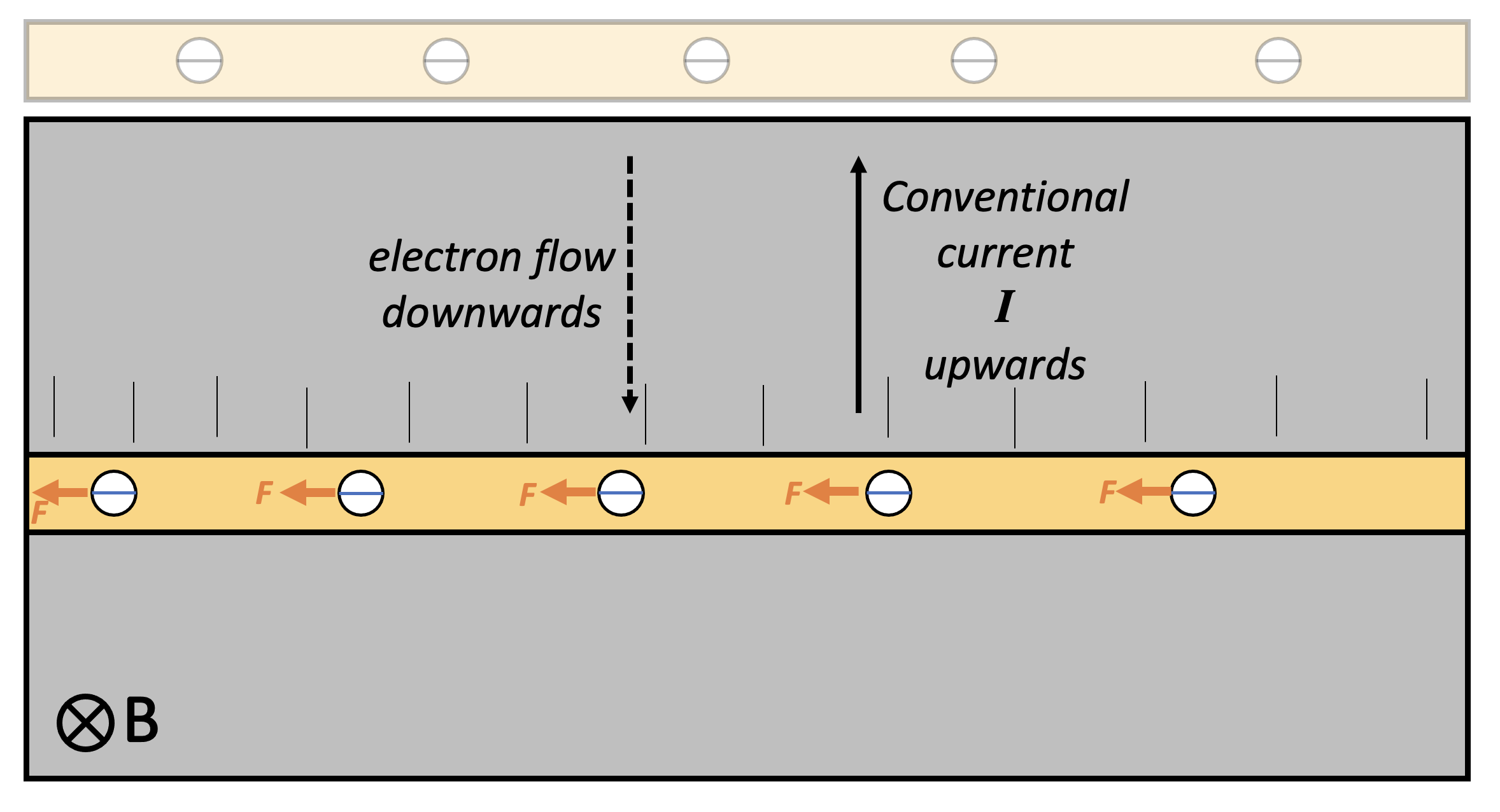
Applying Fleming Left Hand Rule (FLHR) to this instance, we find that each electron experiences a small force tugging it to the left — but only while the conductor is being moved downwards.
This results in the left hand side of the conductor becoming negatively charged and the right hand side becoming positively charged: in short, a potential difference builds up across the conductor. This potential difference only happens when the conductor is moving through the magnetic field in such a way that the electrons are tugged towards one end of the conductor. (There is, of course, the Hall Effect in some other instances, but we won’t go into that here.)
As soon as the conductor stops moving, the potential difference is no longer induced as there is no ‘charge flow’ through the magnetic field and, hence, no current and no FLHR motor effect force acting on the electrons.
Faraday’s model of electromagnetic induction
Michael Faraday (1791-1867) discovered the phenomenon of electromagnetic induction in 1831 and explained it using the idea of a conductor cutting magnetic field lines. This is an immensely valuable model which not only explains EMI but can also generate quantitative predictions and, yes, it should definitely be taught to students — but perhaps the approach outlined above is better to introduce EMI to students.
The left hand rule not knowing what the right hand rule is doing . . .
We usually apply Fleming’s Right Hand Rule (FRHW) to cases of EMI, Can we replace its use with FLHR? Perhaps, if you wanted to. However, FRHR is a more direct and straightforward shortcut to predicting the direction of conventional current in this type of situation.

Love it. I think? Where’s the Emerson quote? ILYF xxxx
“It just seems such a random, free floating and unconnected fact.” I think that the Mark Scheme would award 3 Marks for that statement. In fact, it sums up the entire topic of electromagnetism as taught for GCSE.
I read your section on using FLHR to arrive at FRHR with interest, trying to find fault with it. It certainly gives the right answer but if the student’s ‘kinetic energy store’ is being used to generate electrical power, then there should be a force in the direction of the ‘conventional current’ arrow otherwise the student would be generating power with no effort. Indeed, if we apply FLHR to the current being induced in the conductor, we do predict the required upward force. So double-plus good.
So, Fleming’s hands are connected and the number of ‘random, free floating and unconnected facts’ may be reduced by one. However there is only one Law of Electromagnetic Induction and one Law of Conservation of Energy so how can we apply the same argument to a transformer? (In my blog I drew a sketch of a device that could be a motor, or a generator, or a transformer.)
WordPress does not allow me to reproduce it here but it can be found on Page19 (fig 3.21) at: https://agrumpyoldphysicstechnician.wordpress.com/2020/04/25/electrical-machinery-more-about-electrical-machinery/
So it should be possible but the configuration is very different; the conductor is passing through the flux in your diagram whereas the conductor runs around the flux in a transformer. It is straightforward to explain the operation of a transformer from the above two laws and thence derive the flux-cutting model and Fleming’s Rules, finishing with the mnemonics for the digits; but the reverse procedure is beyond me.
Finally, a personal anecdote: the variation on Fleming’s Rules that I have used for 40 years came from ‘Wireless World’, it only involved the use of one hand; later I found that AQA required not only knowledge of both left hands but to be able to say which of the first three thumbs represented each quantity.
Thanks for your interest and comment! Yes, you’re right. As I understand it, there *will* be a force in the direction of the conventional current arrow. The faster they move the wire downwards, then the larger this ‘opposition’ force. The direction of the force is predicted by Lenz’s Law: “The direction of the induced EMF is such that it will oppose the change producing it.” I think Lenz’s Law is simply a restatement of the conservation of energy: if Lenz’s Law were not true, then the student would indeed get ‘current for nothing’; instead they have to work *harder* if they generate a large current by moving the conductor faster (and the size of the current flow would depend on the induced EMF and the resistance of the external circuit). I’m not quite sure I follow your line of argument with electric motors: simple DC motors with a perm magnet (at least from what I’ve observed) do turn faster with (a) more current (usually produced by a turning up the supply p.d.) and (b) more turns (assuming that you compensate for any increase in resistance). Admittedly, I have very limited experience with AC motors or motors without perm magnets. Happy to discuss this topic further and talk about transformers if you wish.
Yes, Lenz’s Law is just a particular case of the conservation of energy. But that is the point, the purpose of electromagnetic machines is to transform electrical or mechanical energy, at the input, to electrical or mechanical energy, at the output. School textbooks tend to be vague about this and start talking about electric current and magnetic flux as though these terms are synonymous with energy. Explanations generally concentrate on the quantity of energy at the output but are weak on how the system determines the required quantity of energy at the input.
Your observation that a simple DC motor speeds up when the input voltage is increased is perfectly in accord with theory. The difficulty comes in determining what effect this has on the current drawn. For an ideal motor, the speed depends on the input voltage and the current depends on the torque presented by the load on the output; voltage and current are thus independent. This is approximately true for an efficient (and hence large) motor but is far from true for an inefficient one. In the school laboratory, torque is not only not usually measured but can vary wildly with speed and other conditions.
The simplest way of increasing the current is to increase the mechanical load on the output; this also has the effect of slowing the speed. Just to further confound matters, the speed can also be deceased by increasing the strength of the magnetic field or by increasing the number of turns. At this point the textbook is only good for kindling.
So much for motors; school textbook authors have no difficulty in saying that increasing the number of turns or increasing the field strength causes the output voltage to increase when the same motor is used as a generator. Somehow they miss that the same equations apply however the machine is used.
Spoiler alert: engineering textbooks get it right and machines keep on obeying the laws of physics regardless of what anyone thinks.
I am more than happy to discuss this further. The link in my previous post is to a series of posts that, apart from being a rant about school textbooks and examiners, does contain my thoughts of the subject. The surprising think is just how simply everything just falls into place.