Do we delve deeply enough into the actual physical mechanism of current flow through electrical conductors (in terms of charge carriers and electric fields) in our treatments for GCSE and A-level Physics? I must reluctantly admit that I am increasingly of the opinion that the answer is no.
Of course, as physics teachers we talk with seeming confidence of current, potential difference and resistance but — when push comes to shove — can we (say) explain why a bulb lights up almost instantaneously when a switch several kilometres away is closed when the charge carriers can be shown to be move at a speed comparable to that of a sedate jogger? This would imply a time delay of some tens of minutes between closing the switch and energy being transferred from the power source (via the charge carriers) to the bulb.
When students asked me about this, I tended to suggest one of the following:
- “The electrons in the wire are repelling each other so when one close to the power source moves, then they all move”; or
- “Energy is being transferred to each charge carrier via the electric field from the power source.”
However, to be brutally honest, I think such explanations are too tentative and “hand wavy” to be satisfactory. And I also dislike being that well-meaning but unintentionally oh-so-condescending physics teacher who puts a stop to interesting discussions with a twinkly-eyed “Oh you’ll understand that when you study physics at degree level.” (Confession: yes, I have been that teacher too often for comfort. Mea culpa.)
Sherwood and Chabay (1999) argue that an approach to circuit analysis in terms of a predominately classical model of electrostatic charges interacting with electric fields is very helpful:
Students’ tendency to reason locally and sequentially about electric circuits is directly addressed in this new approach. One analyzes dynamically the behaviour of the *whole* circuit, and there is a concrete physical mechanism for how different parts of the circuit interact globally with each other, including the way in which a downstream resistor can affect conditions upstream.
(Side note: I think the Coulomb Train Model — although highly simplified and applicable only to a limited set of “steady state” situations — is consistent with Sherwood and Chabay’s approach, but more on that later.)
Misconception 1: “The electrons in a conductor push each other forwards.”
On this model, the flowing electrons push each other forwards like water molecules pushing neighbouring water molecules through a hose. Each negatively charged electron repels every other negatively charged electron so if one free electron within the conductor moves, then the neighbouring free electrons will also move. Hence, by a chain reaction of mutual repulsion, all the electrons within the conductor will move in lockstep more or less simultaneously.
The problem with this model is that it ignores the presence of the positively charged ions within the metallic conductor. A conveniently arranged chorus-line of isolated electrons would, perhaps, behave analogously to the neighbouring water molecules in a hose pipe. However, as Sherwood and Chabay argue:
Averaged over a few atomic diameters, the interior of the metal is everywhere neutral, and on average the repulsion between flowing electrons is canceled by attraction to positive atomic cores. This is one of the reasons why an analogy between electric current and the flow of water can be misleading.

Misconception 2: “The charge carriers move because of the electric field from the battery.”
Let’s model the battery as a high-capacity parallel plate capacitor. This will avoid the complexities of having to consider chemical interactions within the cells. Think of a “quasi-steady state” where the current drawn from the capacitor is small so that electric charge on the plates remains approximately constant; alternatively, think of a mechanical charge transfer mechanism similar to the conveyor belt in a Van de Graaff generator which would be able to keep the charge on each plate constant and hence the potential difference across the plates constant (see Sherwood and Chabay 1999: 5).

This is not consistent with what we observe. For example, if the charge-carriers-move-due-to-electric-field-of the-battery model was correct then we would expect a bulb closer to the battery to be brighter than a more distant bulb; this would happen because the bulb closer to the battery would be subject to a stronger electric field and so we would expect a larger current.

There is the additional argument if we orient the bulb so that the current flow is perpendicular to the electric field line, then there should be no current flow. Instead, we find that the orientation of the bulb relative to the electric field of the battery has zero effect on the brightness of the bulb.
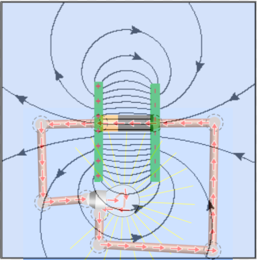
Since we do not observe these effects, we can conclude that the electric field lines from the battery are not solely responsible for the current flow in the circuit.
Understanding the cause of current flow
If the electric field of the battery is not responsible on its own for the potential difference that causes a current to flow, where does the electric field come from?
Interviews reveal that students find the concept of voltage difficult or incomprehensible. It is not known how many students lose interest in physics because they fail to understand basic concepts. This number may be quite high. It is therefore astonishing that this unsatisfactory situation is accepted by most physics teachers and authors of textbooks since an alternative explanation has been known for well over one hundred years. The solution […] was in principle discovered over 150 years ago. In 1852 Wilhelm Weber pointed out that although a current-carrying conductor is overall neutral, it carries different densities of charges on its surface. Recognizing that a potential difference between two points along an electric circuit is related to a difference in surface charges [is the answer].
Härtel (2021): 21
We’ll look at these interesting ideas in part two.
[Note: this post edited 10/7/22 because of a rewritten part two]
References
Härtel, H. (2021). Voltage and Surface Charges. European Journal of Physics Education, 12(3), 19-31.
Sherwood, B. A., & Chabay, R. W. (1999). A unified treatment of electrostatics and circuits. URL http://cil. andrew. cmu. edu/emi. (Note: this article is dated as 2009 on Google Scholar but the text is internally dated as 1999)
Acknowledgements
The circuit representations were produced using the excellent PhET Sims circuit simulator.
I was “awoken from my dogmatic slumbers” on this topic (and alerted to Sherwood and Chabay’s treatment) by Youtuber Veritasium‘s provocative videos (see here and here).

“Since we do not observe these effects, we can conclude that the electric field lines from the battery are not solely responsible for the current flow in the circuit.” – wrong. Your error is in assuming that the electric field looks like what’s shown in the picture. The picture shows electric field of a capacitor in vacuum, or some other homogeneous environment. In reality the environment is not homogeneous. The conductors connected to the capacitor have a much higher permittivity than the surrounding air, and this govenrs the shape of the electric field lines. Unsurprisingly, the field lines are constrained to the conductors (and their near vicinity), which is why it doesn’t matter how far the light bulb is from the capacitor or which way is it rotated.
I don’t think that the electric field of the cell (or other source of emf) *alone* can account for current flow in conductors even if we take into account different permittivity of various circuit element — I think these might very well affect the magnitude of the electric field at that location but I don’t think it could affect the direction. Sherwood and Chabay (1999: 3) make what I think is a convincing argument when they consider what would happen if (say) a lit bulb connected to a battery was rotated by 90 degrees: “Moreover, if we rotate the socket by 90 degrees (with the wires remaining attached), the electric field due to the battery charges should now be perpendicular to the filament, and there should be little or no current, yet we don’t see any change in the brightness of the bulb.Evidently charges in and on the battery cannot be the only source of the electric field inside the bulb filament. There is a deep puzzle: where are the charges that are the source of the electric field inside the bulb filament?” They then go on to argue that this internal electric field is generated by small electric charges distributed over the surface of the conductors.
my teacher said you ain’t reliable
🙁 Why not?