Do we delve deeply enough into the actual physical mechanism of current flow through electrical conductors using the concepts of charge carriers and electric fields in our treatments for GCSE and A-level Physics? I must reluctantly admit that I am increasingly of the opinion that the answer is no.
In part one we discussed two common misconceptions about the physical mechanism of current flow, namely:
- The all-the-electrons-in-a-conductor-repel-each-other misconception; and
- The electric-field-of-the-battery-makes-all-the-charge-carriers-in-the-circuit-move misconception.
In part two we looked at how the distribution of surface charges on electrical conductors produces the internal electric fields that guide and push charges around electric circuits and highlighted the published evidence that supports this model.

In part three, we are going to look at the transient processes that produce the required distribution of surface charges. In this treatment, I am going to lean very heavily on the analysis presented in Duffin (1980: 167-8).
Connecting wires to a chemical cell
Let’s connect up a simple circuit using a chemical cell as our source of EMF ℰ.
The first diagram shows the cell and wires before they are connected.

When the wires are connected there is a momentary current flow from the cell that creates the surface charge distribution shown below.

The current will stop when the ends of the wire at a potential difference V which is equal to the EMF ℰ of the cell. The ends of the wire act as a small capacitor (∼10-15 F or less). The wires act as equipotential volumes so the very small charge must be distributed over the surface of the wires with a slight concentration of charge at the ends.
Making the circuit
If the ends of the wire are now connected, then the capacitance drops to zero and the ends of the wires become discharged. This leads to very low concentration of surface charge in this region.
However, just enough surface charge remains to produce the internal electric field as shown below. The field lines of the internal electric field are parallel to the wire.
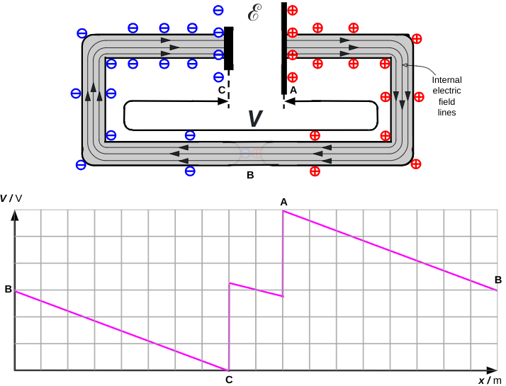
The potential diagram is after Figure 6.17 (Duffin 1980: 160). The ‘dip’ between C and A is due to the effect of the internal resistance of the cell. As we can see in this instance, when there is a steady flow of current then V is slightly smaller than ℰ.
Reference
Duffin, W. J. (1980). Electricity and magnetism (3rd ed.). McGraw Hill Book Co

I like it. I think. Emerson. ILYF xxxx
Makes a change from “Cicero” LOL
I think I shall write the next one on how much better Pliny is than Cicero…
Another worthwhile addition – much appreciated. You are one of the few reliables in the twitter/blog space. I don’t always agree 100% but I love the way you write and make me think about the underlying Physics. Surface charge approach does make me wonder about adapting/modifying the Coulomb Train though – https://upload.wikimedia.org/wikipedia/commons/d/d1/Biswa_Ijtema_Dhaka_Bangladesh_24012010.JPG
Thank you so much! I think the coulomb train is consistent with surface charge model — with or without the modifications you suggest *Laughing face emoji*
I would argue that there should be a single straight line between C and A. No reason why it should increase at the anode from 0 to over 50% in almost zero “time” (distance actually), then steadily drop due to internal resistance, then suddenly increase again at the cathode all the way to 100%. More likely the potential increases steadily over the whole battery (or capacitor or whatever) so we can just subtract the voltage drop due to internal resistance over the whole distance and show the potential increase as a single straight line. On second thought, it’s probably shown the way it is just for didactic reasons. Still, it would be worth mentioning this…
Fair point. The diagram is after Fig 6.17 from Duffin 1980: 160 which is less symmetrical than my version because the cell is placed off-centre on a straight section of conductor (not a full circuit) so the potential drop on the negative side of the cell is greater than that on the positive side. Since I placed the cell in the centre of my diagram I opted to make everything as symmetrical as possible. I think that you are probably right that the ‘dip’ could plausibly be placed in other positions.
What do you think will happen if we connect only of the the terminals of the battery to a wire? Will the charges on that one wire still redistribute?