Do we delve deeply enough into the actual physical mechanism of current flow through electrical conductors using the concepts of charge carriers and electric fields in our treatments for GCSE and A-level Physics? I must reluctantly admit that I am increasingly of the opinion that the answer is no.
In part one we discussed two common misconceptions about the physical mechanism of current flow, namely:
- The all-the-electrons-in-a-conductor-repel-each-other misconception; and
- The electric-field-of-the-battery-makes-all-the-charge-carriers-in-the-circuit-move misconception.
In part two we looked at how the distribution of surface charges on electrical conductors produces the internal electric fields that guide and push charges around electric circuits and highlighted the published evidence that supports this model.

In part three, we are going to look at the transient processes that produce the required distribution of surface charges. In this treatment, I am going to lean very heavily on the analysis presented in Duffin (1980: 167-8).
Connecting wires to a chemical cell
Let’s connect up a simple circuit using a chemical cell as our source of EMF ℰ.
The first diagram shows the cell and wires before they are connected.

When the wires are connected there is a momentary current flow from the cell that creates the surface charge distribution shown below.

The current will stop when the ends of the wire at a potential difference V which is equal to the EMF ℰ of the cell. The ends of the wire act as a small capacitor (∼10-15 F or less). The wires act as equipotential volumes so the very small charge must be distributed over the surface of the wires with a slight concentration of charge at the ends.
Making the circuit
If the ends of the wire are now connected, then the capacitance drops to zero and the ends of the wires become discharged. This leads to very low concentration of surface charge in this region.
However, just enough surface charge remains to produce the internal electric field as shown below. The field lines of the internal electric field are parallel to the wire.
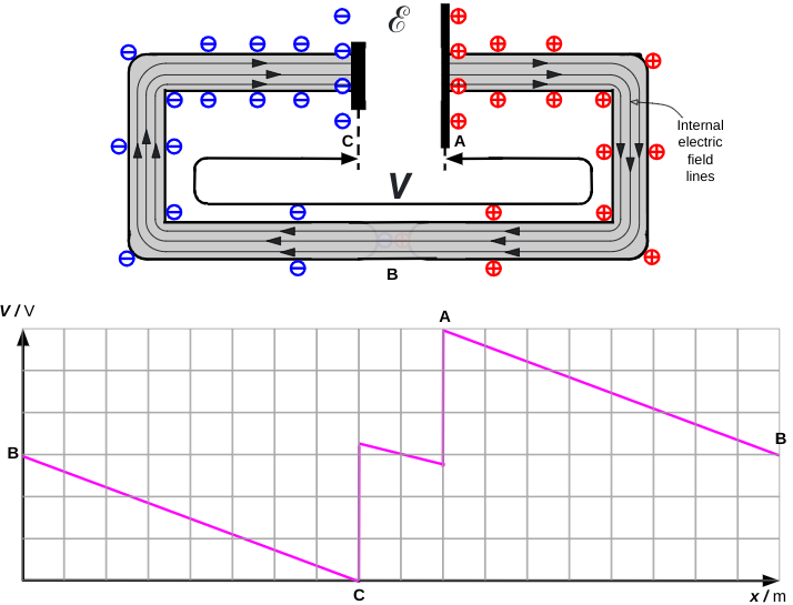
The potential diagram is after Figure 6.17 (Duffin 1980: 160). The ‘dip’ between C and A is due to the effect of the internal resistance of the cell. As we can see in this instance, when there is a steady flow of current then V is slightly smaller than ℰ.
Reference
Duffin, W. J. (1980). Electricity and magnetism (3rd ed.). McGraw Hill Book Co
