
Are physics teachers following the Way of the Sith? Are we all crossing over to the Dark Side when we talk about ‘series circuits’ and ‘parallel circuits’?
I think that, without meaning to, we may be presenting students with what amounts to a false dichotomy: that all circuits are either series circuits or parallel circuits.
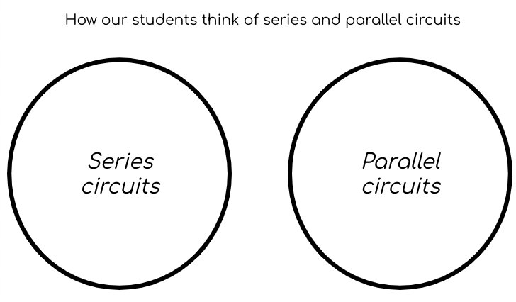
The actual situation is more like this:

The confusion may stem from our usage of the word ‘circuit’: are we referring holistically to the entire assemblage of components (highlighted in red) or the individual ‘complete circuits’ (highlighted in green and blue)?

How to avoid the false dichotomy
I think we should always refer to components in series or components in parallel rather than ‘series circuits’ or ‘parallel circuits’.
Teaching components in parallel using the ‘all-in-a-row’ circuit convention
I’ve written before about what I think is the confusing ‘hidden rotation’ present in normal circuit diagrams. I find redrawing circuit diagrams using the ‘all-in-a-row’ convention useful for explaining circuit behaviour. For simplicity, we’ll assume that all the resistors in the diagrams that follow have a resistance of one ohm.
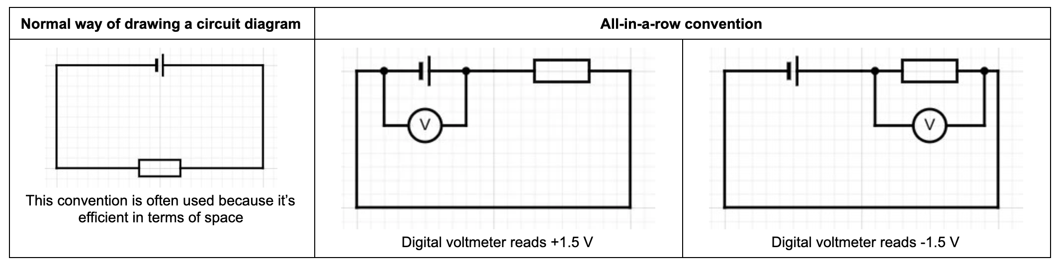
This can be shown using the Coulomb Train Model like this (coulombs pictured as moving clockwise):
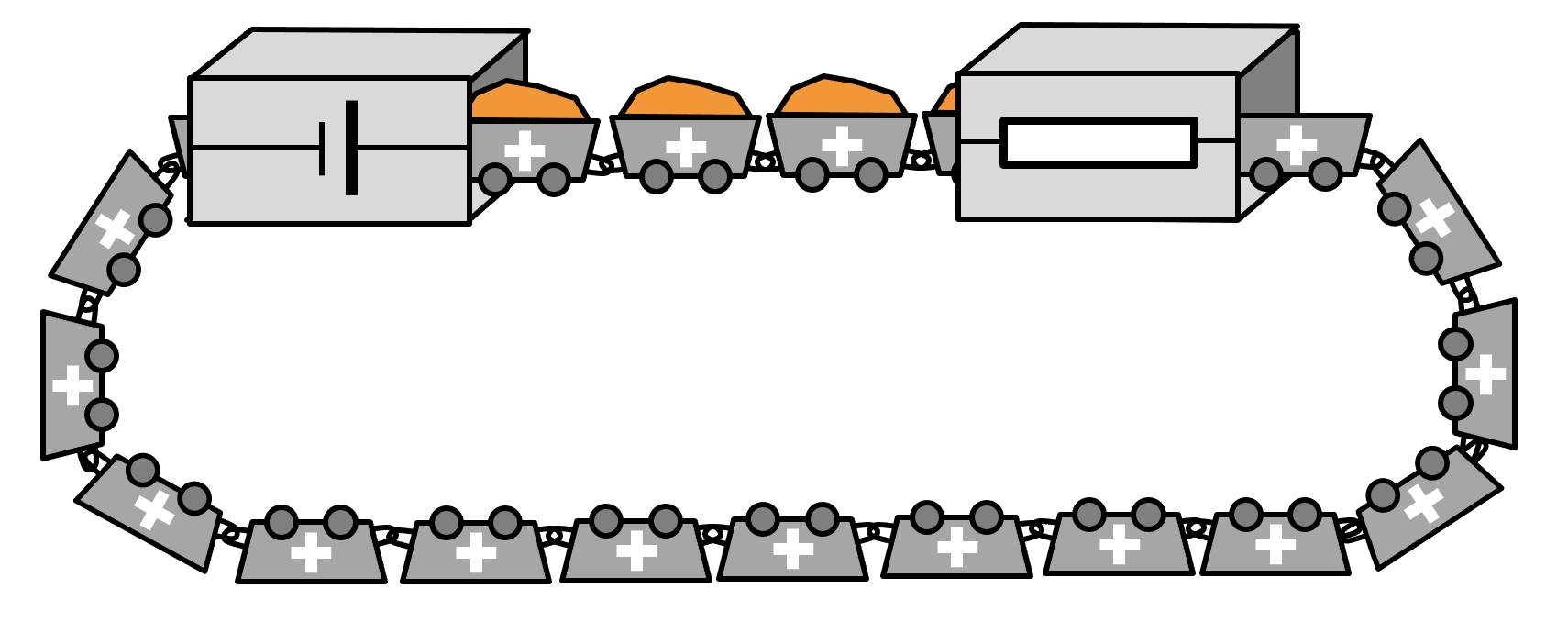
The current passing through the resistor using I = V/R = 1.5 V / 1 = 1.5 amperes.
Now let’s apply this convention when two resistors are in parallel.

This can be represented using the Coulomb Train Model like this:

I think it’s far clearer that ammeter W is measuring the total current in the circuit while X and Y are measuring the ‘part-current’ passing through R1 and R2 using this convention. (Note: we are assuming that each resistor has a resistance of one ohm.)
Each resistor has a potential difference of -1.5 V because 1.5 J of energy is being shifted from each coulomb as they pass through each resistor.
Also, it is clearer that the cell’s chemical energy store is being drained more quickly when there are two resistors in parallel: two coulombs have to be filled with 1.5 J of energy for each one coulomb in the single resistor circuit.
Thinking about current, the total current in the circuit is 3.0 amperes; so the resistance R = V / I = 1.5 / 3.0 = 0.5 ohms. So two resistors in parallel have a smaller resistance than a single resistor — this is a result that is well worth emphasising for students as so many of them find this completely counterintuitive!
Teaching components in series using the all-in-a-row convention

This circuit can be represented using the Coulomb Train Model like this:
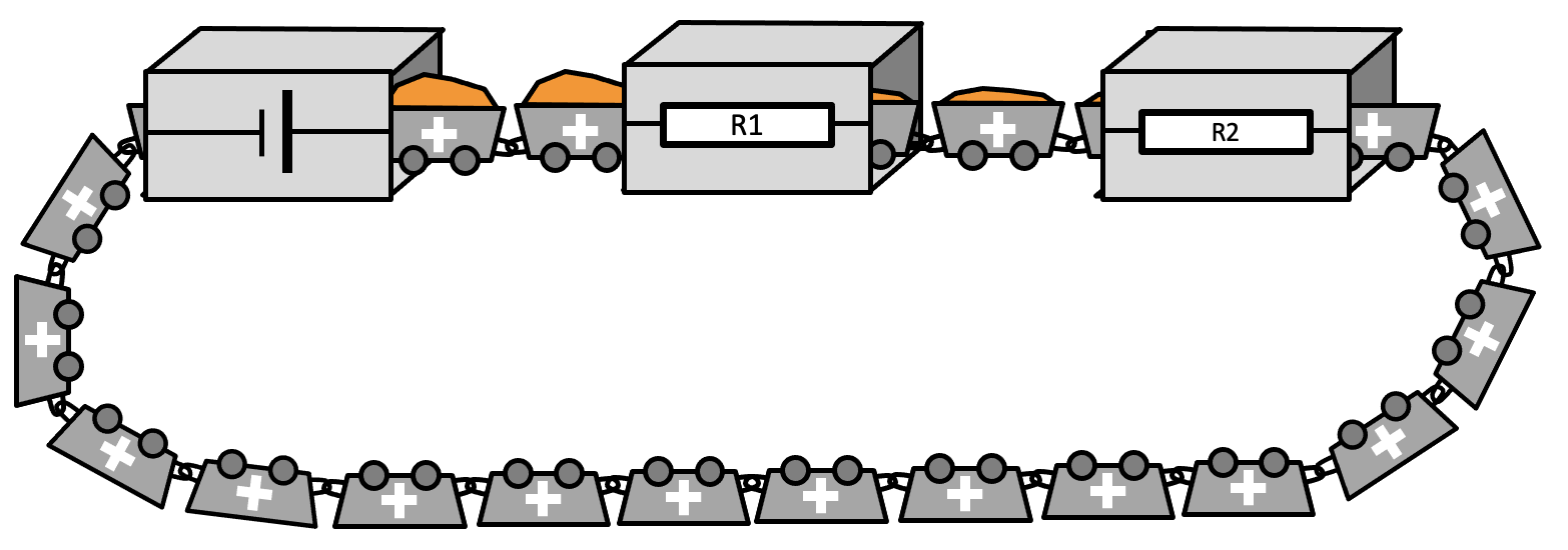
The pattern of potential difference can be explained by looking at the orange ‘energy levels’ carried by each coulomb.
A current of one amp is one coulomb passing per second, so we can see that an ammeter reading would have the same value wherever the ammeter is placed in the circuit.
But look closely at R1: it only has 0.75 V of potential difference across. From I = V/R = 0.75 / 1 = 0.75 amperes.
This means that the total resistance of the circuit from R = V/I is, of course, 2 ohms.
Conclusion
I regret to say that I have probably been teaching ‘series circuits’ and ‘parallel circuits’ on autopilot for much of my career; the same may even be true of some readers of this blog(!)
The Coulomb Train Model has been considered in depth in previous blogs, but I think it’s a good model to encourage students to use their physical intuition (aka ’embodied cognition’) to understand electric circuits.
Whether you agree with the suggested outlines above or not, I hope that it has given you some fruitful food for thought.

Reblogged this on The Echo Chamber.
I really appreciate how you’ve explained things. The diagrams are helpful too. This would definitely make the concept of “Hybrid Circuit” easier for even the layperson to understand.
Thank you! I really appreciate the time you’ve taken to write a comment.