You can read Part 1 which introduces the idea of free body force diagrams here.
Essentially the technique we will use is as follows:
- Draw a situation diagram with NO FORCE ARROWS.
- ‘Now let’s look at the forces acting on just object 1’ and draw a separate free body diagram (i.e. a diagram showing just object 1 and the forces acting on it)
- Repeat step 2 for some or all of the other objects at your discretion.
- (Optional) Link all the diagrams with dotted lines to emphasise that they are facets of a more complex, nuanced whole
The Wheel Thing
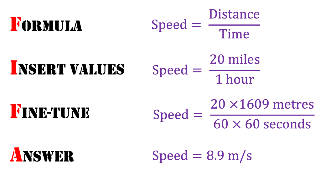
Let’s consider a car travelling at a constant velocity of 20 miles per hour.

’20 m.p.h.’ is such an uncivilised unit so let’s use the FIFA system to change it into more civilised scientific S.I. units:

Note that point A on the car tyre is moving at 8.9 m/s due to the rotation of the wheel, as well as moving at 8.9 m/s with the rest of the car. This means that point A is moving at 8.9 + 8.9 = 17.8 m/s relative to the ground.
More strangely, point B on the car tyre is moving backwards at speed of 8.9 m/s due to the rotation of the wheel, as well as moving forwards at 8.9 m/s with the rest of the car. Point B is therefore momentarily stationary with respect to the ground.
The tyres can therefore ‘grip’ the road surface because the contact points on each tyre are stationary with respect to the road surface for the moment that they are in position B. If this was not the case, then the car would be difficult to control as it would be in a skid.
(Apologies for emphasising this point — I personally find it incredibly counterintuitive! Who says wheels are not technologically advanced!)
Forces on a tyre
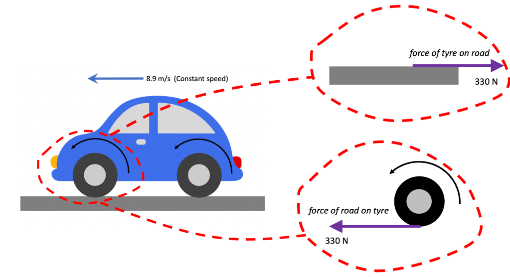
Assuming the car in the diagram is a four wheel drive, the total force driving it forward would be 4 x 330 N = 1320 N. Since it is travelling at a constant speed, this means that there is zero resultant force (or total force). We can therefore infer that the total resistive force acting on the car is 1320 N.
It is can also be slightly disconcerting that the force driving the car forward is a frictional force because we usually speak of frictional forces having a tendency to ‘oppose motion’.
And so they are in this case also. The movement they are opposing is the relative motion between the tyre surface and the road. Reduce the frictional force between the road with oil or mud, and the tyre would not ‘lock’ on the surface and instead would ‘spin’ in place. It’s worth bearing in mind (and communicating to students) that the tread pattern on the tyre is designed to maximise the frictional force between the tyre surface and the road
And then a step to the right…
It’s just a jump to the left
And then a step to the right
The Time Warp, Rocky Horror Picture Show

We can see how important friction is for taking a step forward in the above diagrams. Again, it is worth pointing out to students how much effort goes into designing the ‘tread’ on certain types of footwear so as to maximise the frictional force. On climbing boots, the ‘tread’ extends on to the upper surface of the boot for that very reason.

One step beyond
Let’s apply a similar analysis to the case of a person stepping off a boat that happens not be tied to the mooring.

The person pushes back on the boat (gripping the boat with friction as above). By Newton’s Third Law, this generates an equal an opposite force on the boat. There is no horizontal force to the right due to the tension in the rope, since there is no rope(!) This means that there is a resultant force on the boat to the left so the boat accelerates to the left.
The forces on the person and the boat will be equal in magnitude, but the acceleration will depend on the mass of each object from F = ma.
Since the boat (e.g. a rowing boat) is likely to have a smaller mass than the person, its acceleration to the left will be higher in magnitude than the acceleration of the person to the right — which will lead to the unfortunate consequence shown below.

The acceleration of the person and the boat happens only when the person and boat are in contact with each other, since this is the only time when there will be a resultant force in the horizontal direction.
Note that although force arrows on a situation diagram should be discouraged for the sake of clarity, there is an argument for drawing velocity and acceleration arrows on the situation diagram as a form of dual coding. Further details can be found here, and an explanation of why acceleration is shown as a double headed arrow.
The velocity to the left built up by the boat in this short instant will be greater than the velocity to the right built up by the person, because the acceleration of the boat is greater, as argued above.
The outcome, of course, is that the person falls in the water, which has been the subject of countless You’ve Been Framed clips.
Next post…
In the next post, I will try to move beyond horizontal forces and take account of the normal reaction force when an object rests on both horizontal surfaces and inclined surfaces.
